Tape measure apparatus which can be used as a marking gauge and/or compass
What is Al technical title?
Al technical title is built by PatSnap Al team. It summarizes the technical point description of the patent document.
a technology of measuring apparatus and tape measure, which is applied in the field of tape measure apparatus, can solve the problems of restricted utility of tape measure apparatus
Inactive Publication Date: 2006-02-14
RICALDE PAUL
View PDF37 Cites 52 Cited by
Summary
Abstract
Description
Claims
Application Information
AI Technical Summary
This helps you quickly interpret patents by identifying the three key elements:
Problems solved by technology
Method used
Benefits of technology
[0018]The apparatus of the present invention solves the problems confronted in the art in a simple and straightforward manner. What is provided in one embodiment is an adapter for tape measures which, after insertion, enables standard tape measures to be used as marking gauges and / or compasses. Another embodiment includes a tape measure apparatus with the casing being redesigned and / or adapted to include an insert enabling the tape measure to be used as a marking gauge and / or compass.
Problems solved by technology
Tape measures are well adapted for measuring distances but their utility is usually restricted to this single function.
Method used
Image
Click on the blue label to locate the original text in one second.
Reading with bidirectional positioning of images and text.
Examples
Embodiment Construction
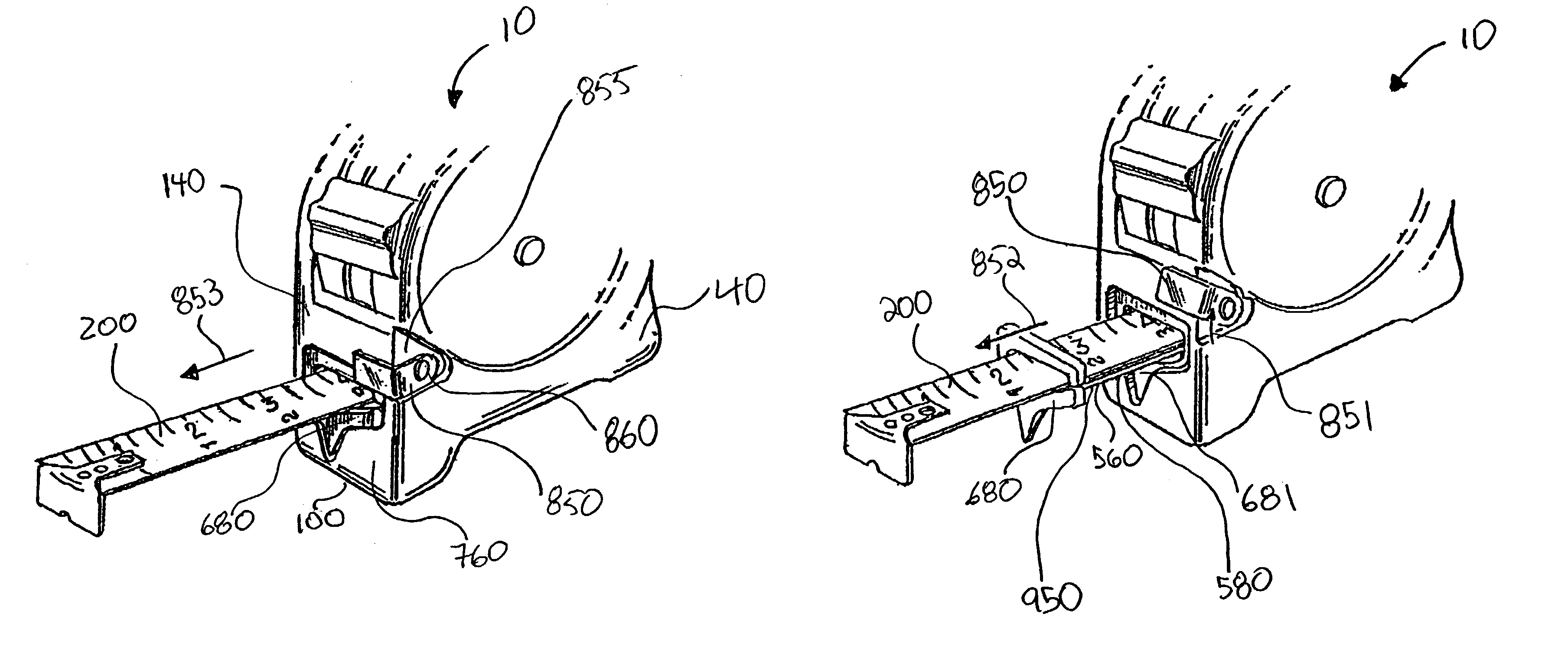
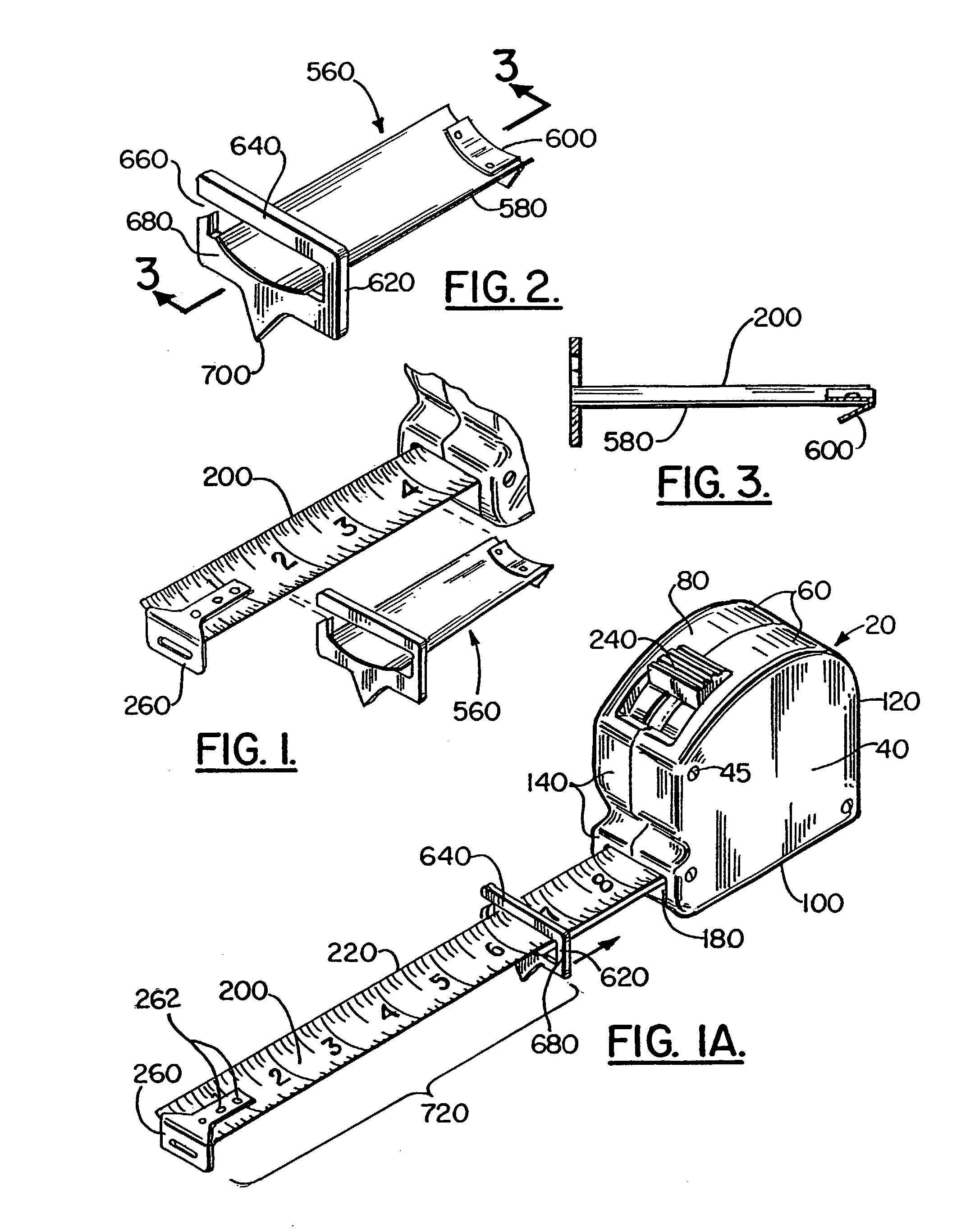
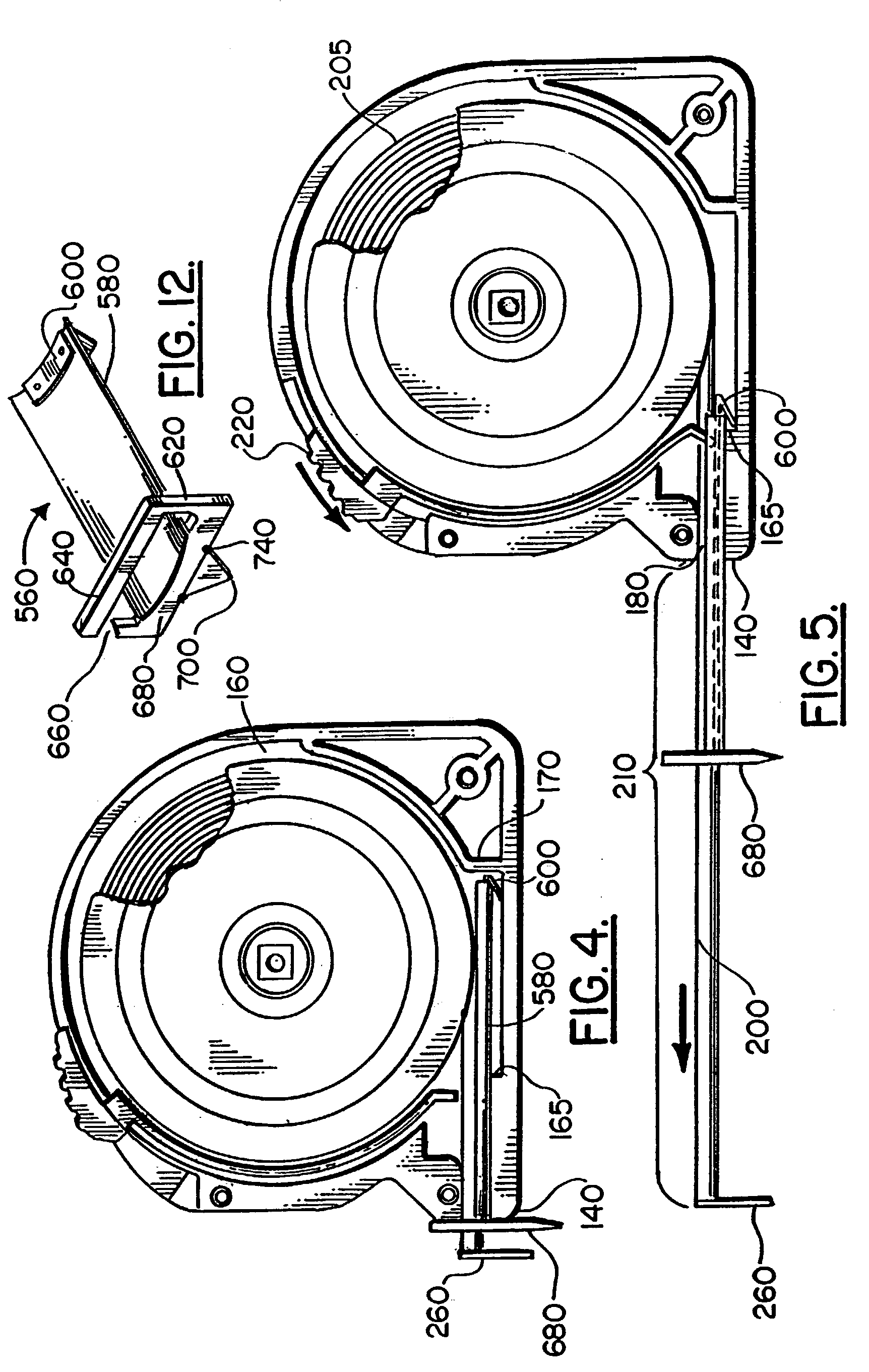
[0055]FIGS. 1 through 6 show an embodiment of the apparatus of the present invention, designated generally by the numeral 10 in FIGS. 1, 1A, 4 and 5. FIGS. 1 through 5 illustrate tape measure apparatus 10 which can include a conventional type tape measure 20 comprising a casing 40 having two side walls 60, a top wall 80, a bottom wall 100, a rear wall 120 and a front wall 140 defining enclosure 160. Front wall 140 has a rule blade aperture 180 adjacent to bottom wall 100. Rule blade 200 is normally retractably stored in a coiled condition within enclosure 160 of casing 40. An inner end 205 of rule blade 200 is secured within enclosure 160, while an outer end 210 of rule blade 200 protrudes through blade aperture 180 in casing 40. Graduated indicia markings 220 along the length of the rule blade 200 function as a measuring scale.
[0056]A lock and automatic rewind switch 240 can be carried on top wall 80 or front wall 140 of casing 40, to keep a portion of rule blade 200 in an extended...
PUM
Abstract
An improved tape measure apparatus which can be used as a marking gauge and/or compass comprising a tape measure, an insert comprising a base, a guide attached to the base and generally parallel to graduated indicia markings of the rule blade when extended from the tape measure whereby the graduated markings of the tape measure's rule blade may be read. An alternative embodiment includes an insert enabling standard tape measures to be used as marking gauges and/or compasses.
Description
CROSS-REFERENCE TO RELATED APPLICATIONS[0001]This is a continuation-in-part of U.S. patent application No. 09 / 990,897, filed Nov. 16, 2001, now abandoned which was a continuation-in-part of U.S. patent application No. 09 / 561,062, filed Apr. 28, 2000 (which issued as U.S. Pat. No. 6,497,050 on Dec. 24, 2002).[0002]Priority is hereby claimed to U.S. patent application No. 60 / 370,118, filed Apr. 4, 2002.[0003]Priority is hereby claimed to U.S. patent application No. 09 / 990,897, filed Nov. 16, 2001.[0004]Priority is hereby claimed to U.S. patent application No. 60 / 249,777, filed Nov. 17, 2000.[0005]Priority is hereby claimed to U.S. patent application No. 09 / 561,062, filed Apr. 28, 2000.[0006]U.S. patent application No. 60 / 370,118, filed Apr. 4, 2002 is incorporated herein by reference.[0007]U.S. patent application No. 09 / 990,897, filed Nov. 16, 2001 is incorporated herein by reference.[0008]U.S. patent application No. 60 / 249,777, filed Nov. 17, 2000 is incorporated herein by reference....
Claims
Application Information
Patent Timeline
Application Date:The date an application was filed.
Publication Date:The date a patent or application was officially published.
First Publication Date:The earliest publication date of a patent with the same application number.
Issue Date:Publication date of the patent grant document.
PCT Entry Date:The Entry date of PCT National Phase.
Estimated Expiry Date:The statutory expiry date of a patent right according to the Patent Law, and it is the longest term of protection that the patent right can achieve without the termination of the patent right due to other reasons(Term extension factor has been taken into account ).
Invalid Date:Actual expiry date is based on effective date or publication date of legal transaction data of invalid patent.