Sealed spray cooling system

a cooling system and seal technology, applied in the field of electronic cooling systems, can solve the problems of inacceptable thermal gradients, large thermal gradients across the device, and elevated junction temperatures, and achieve the effect of reducing coolant loss

Inactive Publication Date: 2006-02-14
PARKER INTANGIBLES LLC
View PDF8 Cites 31 Cited by
  • Summary
  • Abstract
  • Description
  • Claims
  • Application Information

AI Technical Summary

Benefits of technology

[0013]In view of the foregoing disadvantages inherent in the known types of thermal management systems now present in the prior art, the present invention provides a new sealed spray cooling system construction wherein the same can be utilized for reducing coolant loss within thermal management systems.

Problems solved by technology

For a given device, non-uniform contact leads to elevated junction temperatures, and large thermal gradients across the device.
For an application such as the burn-in of multiple semiconductor devices, such non-uniform contact also creates unacceptable thermal gradients across the batch (leads to large junction temperature spread).
When the equipment being cooled needs to be accessed, for example, for maintenance, there is the chance that such vapor could be lost to the atmosphere.
In any application of spray cooling thermal management, coolant vapor loss is a significant issue.
While conventional thermal management systems may be suitable for the particular purpose to which they address, they are not as suitable for reducing coolant loss.
Conventional spray cooling thermal management systems may have significant coolant vapor loss, which would increase the thermal management costs.

Method used


Image

  • Sealed spray cooling system
  • Sealed spray cooling system
  • Sealed spray cooling system

Examples


first embodiment

B. First Embodiment

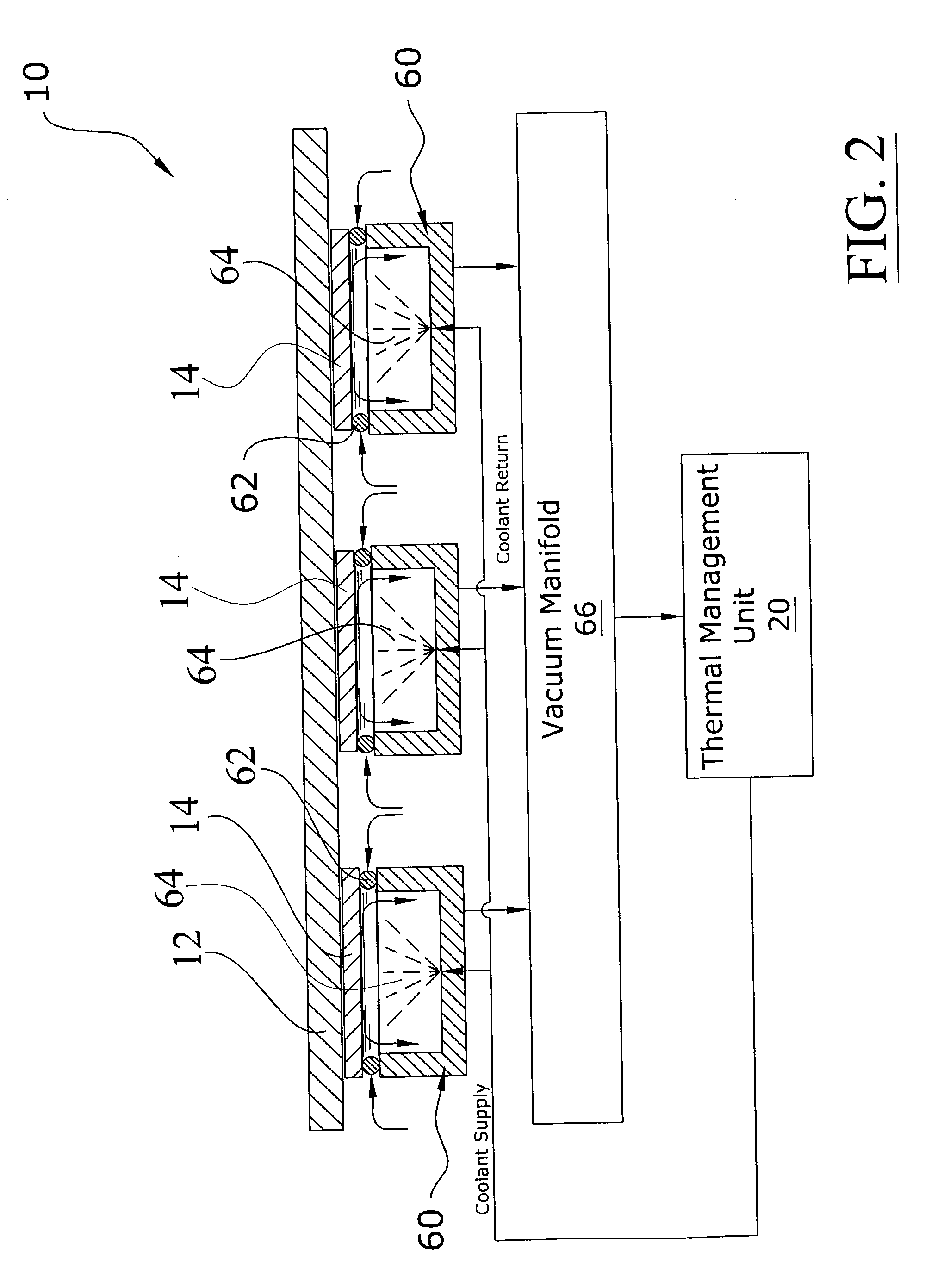
[0041]FIGS. 2 and 3 illustrate a spray unit 60 that has reduced vapor loss. The spray unit 60 utilizes a spray housing for each individual semiconductor 14 that is sealed by a seal structure 62. The seal structure 62 may be comprised of various sealing structures such as O-rings and the like. The seal structure 62 is designed to efficiently seal, for example, on the carrier of a bare device (i.e. does not employ an integrated heat sink), on the integrated heat sink, on the device's socket, or on the printed circuit board to which the device is mounted.

[0042]The spray unit 60 may utilize one or more atomizers in various arrangements. The spray unit 60 is designed to continuously deliver coolant to the device being cooled. The spray unit 60 preferably includes an efficient coolant and vapor drainage structure that prevents flooding of the device being cooled thereby ensuring efficient cooling. The structure of the spray unit 60 also prevents vapor / coolant recirculat...

second embodiment

C. Second Embodiment

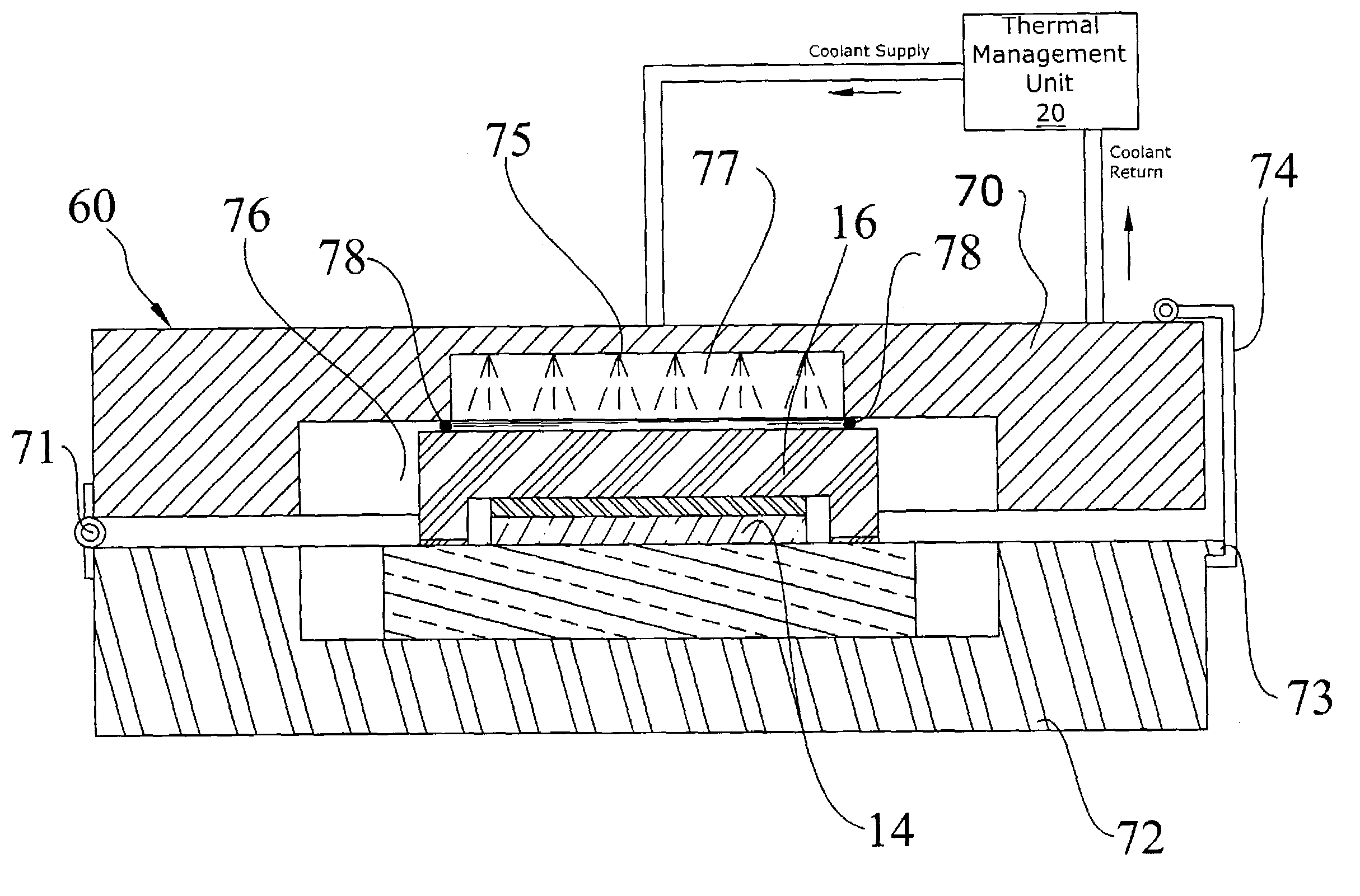
[0045]FIGS. 4 and 5 illustrate an alternative embodiment of the spray units 60 wherein an upper member 70 and a lower member 72 are pivotally attached by a hinge 71. The upper member 70 and the lower member 72 define an interior cavity 76 that receives the semiconductor 14. The lower member 72 may be comprised of a burn-in socket or other structure. A clip member 74 extending from the upper member 70 or other engaging structure selectively engages a lip 73 of the lower member 72 thereby retaining the upper member 70 adjacent the lower member 72.

[0046]The seal member 78 may be comprised of various sealing structures such as O-rings and the like. The seal structure 78 is designed to efficiently seal, for example, on the carrier of a bare device (i.e. does not employ an integrated heat sink), on the integrated heat sink, on the device's socket, or on the printed circuit board to which the device is mounted.

[0047]The spray unit 60 may utilize one or more atomizers in...

third embodiment

D. Third Embodiment

[0049]FIG. 6 illustrates an alternative embodiment of the present invention that is particularly suitable for semiconductor testing procedures. During semiconductor testing procedures, it is often times required to rapidly change the temperature of the semiconductor while adjusting electrical power input into the semiconductor 14. The spray units 60 may be utilized within a single module tester (SMT) environment where the semiconductor's temperature may have to be maintained at a constant or varying level in response to power cycling of the semiconductor 14. In an SMT environment, the semiconductor 14 is simply removed from the spray unit 60.

[0050]As shown in FIG. 6 of the drawings the spray unit 60 has an interior spray cavity with at least one atomizer spraying a coolant directly upon a thermally conducting wall 68. The thermally conducting wall 68 may be integrally formed within the spray unit 60 or attached to the spray unit 60 with insulation 69 or other mate...


PUM


Abstract

A sealed spray cooling system for reducing coolant loss within thermal management systems. The sealed spray cooling system includes a spray housing defining a spray chamber having at least one atomizer and a seal member attached to the spray housing about the spray chamber for sealing against a semiconductor forming a sealed spray area. Alternatively, the spray unit is comprised of a first member, a second member having at least one atomizer, the second member pivotally attached to the first member forming an interior cavity between thereof, and a seal member attached to the second member for sealing against a semiconductor within the first member thereby forming a sealed spray area. A vacuum manifold is preferably fluidly connected to the spray cavity thereby reducing the pressure within the spray cavity.

Description

CROSS REFERENCE TO RELATED APPLICATIONS[0001]I hereby claim benefit under Title 35, United States Code, Section 120 of U.S. patent application Ser. No. 10 / 243,683 filed Sep. 13, 2002 entitled “Semiconductor Burn-In Thermal Management System” and Ser. No. 10 / 371,403 filed on Feb. 19, 2003 “Coolant Recovery System”. This application is a continuation-in-part of the Ser. Nos. 10 / 243,683 and 10 / 371,403 applications. The Ser. Nos. 10 / 243,683 and 10 / 371,403 applications are currently pending. The Ser. Nos. 10 / 243,683 and 10 / 371,403 applications are hereby incorporated by reference into this application.STATEMENT REGARDING FEDERALLY SPONSORED RESEARCH OR DEVELOPMENT[0002]Not applicable to this application.BACKGROUND OF THE INVENTION[0003]1. Field of the Invention[0004]The present invention relates generally to electronics cooling systems and more specifically it relates to a sealed spray cooling system for reducing coolant loss within thermal management systems.[0005]2. Description of the ...

Claims


Application Information

Patent Timeline
Patent Type & Authority Patents(United States)
IPC IPC(8): F25D17/02B05B1/24F25D23/12H01L23/34G01R31/28G05D23/19
CPCH01L23/4735H01L2924/16152H01L2224/32G01R31/2874G05D23/1919
Inventor CADER, TAHIR
Owner PARKER INTANGIBLES LLC
Why Eureka
Try Eureka