Scrolling unit and projection system using the same

a projection system and scrolling technology, applied in the field of scrolling units and projection systems, can solve the problems of degrading yield, bulky optical system, and single-panel projection systems providing only 13 of the optical efficiency of three-panel projection systems

Inactive Publication Date: 2006-02-14
SAMSUNG ELECTRONICS CO LTD
View PDF7 Cites 4 Cited by
  • Summary
  • Abstract
  • Description
  • Claims
  • Application Information

AI Technical Summary

Benefits of technology

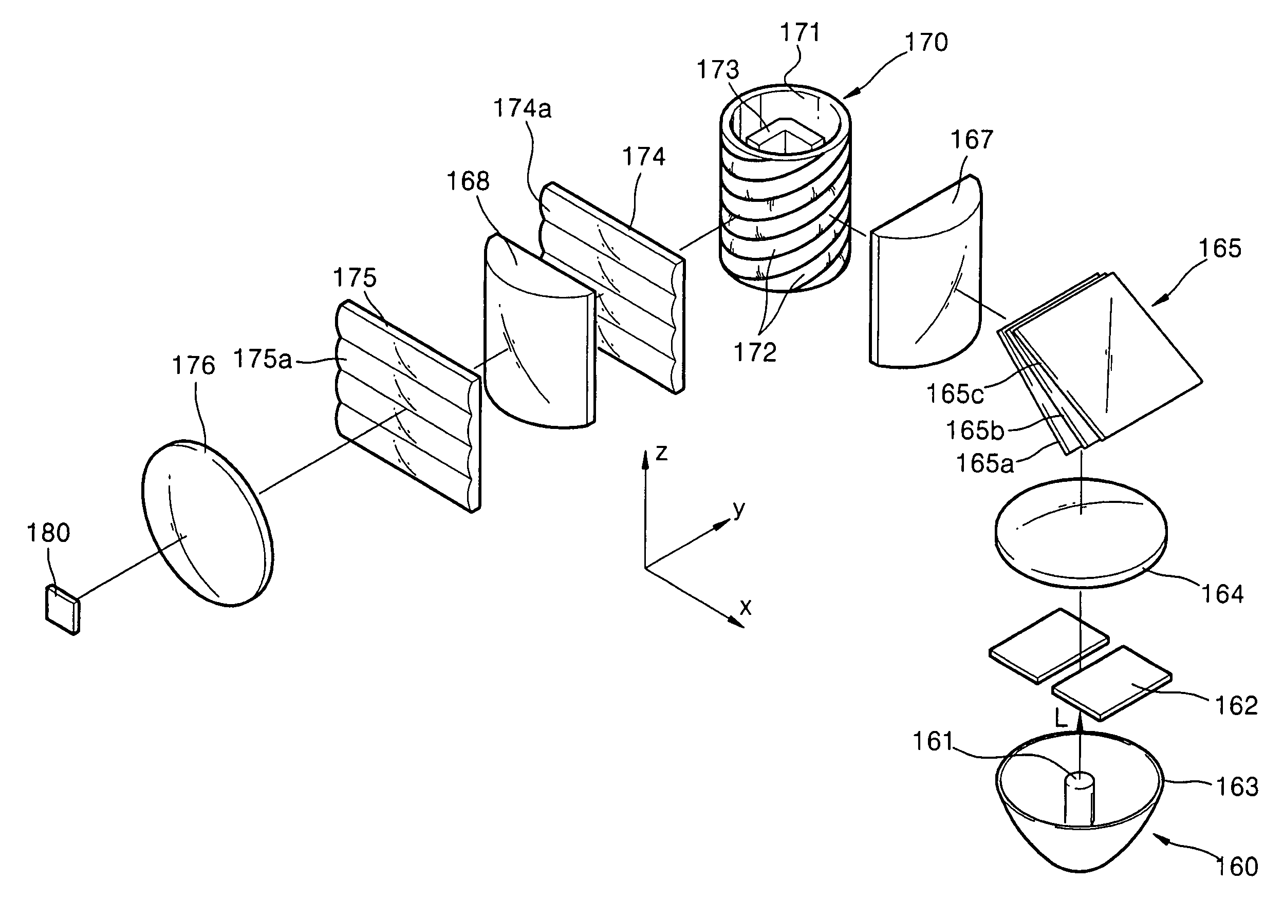
[0015]An apparatus consistent with the present invention provides a scrolling unit in a compact projection system which is formed by spirally arranging at least one cylindrical lens cell on an outer circumferential surface of a column-like plate and installed on a single light path so that color scrolling is achieved.

Problems solved by technology

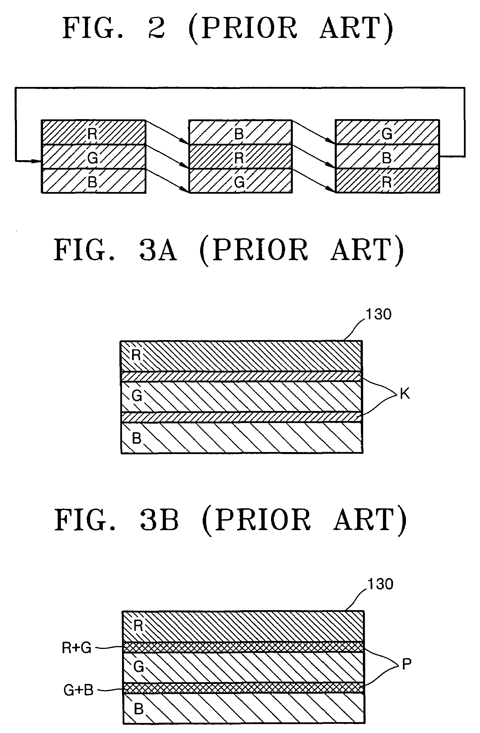
However, these single-panel projection systems provide only ⅓ of the optical efficiency of the three-panel projection systems because red (R), green (G), and blue (B) colors into which white light is separated are used sequentially.
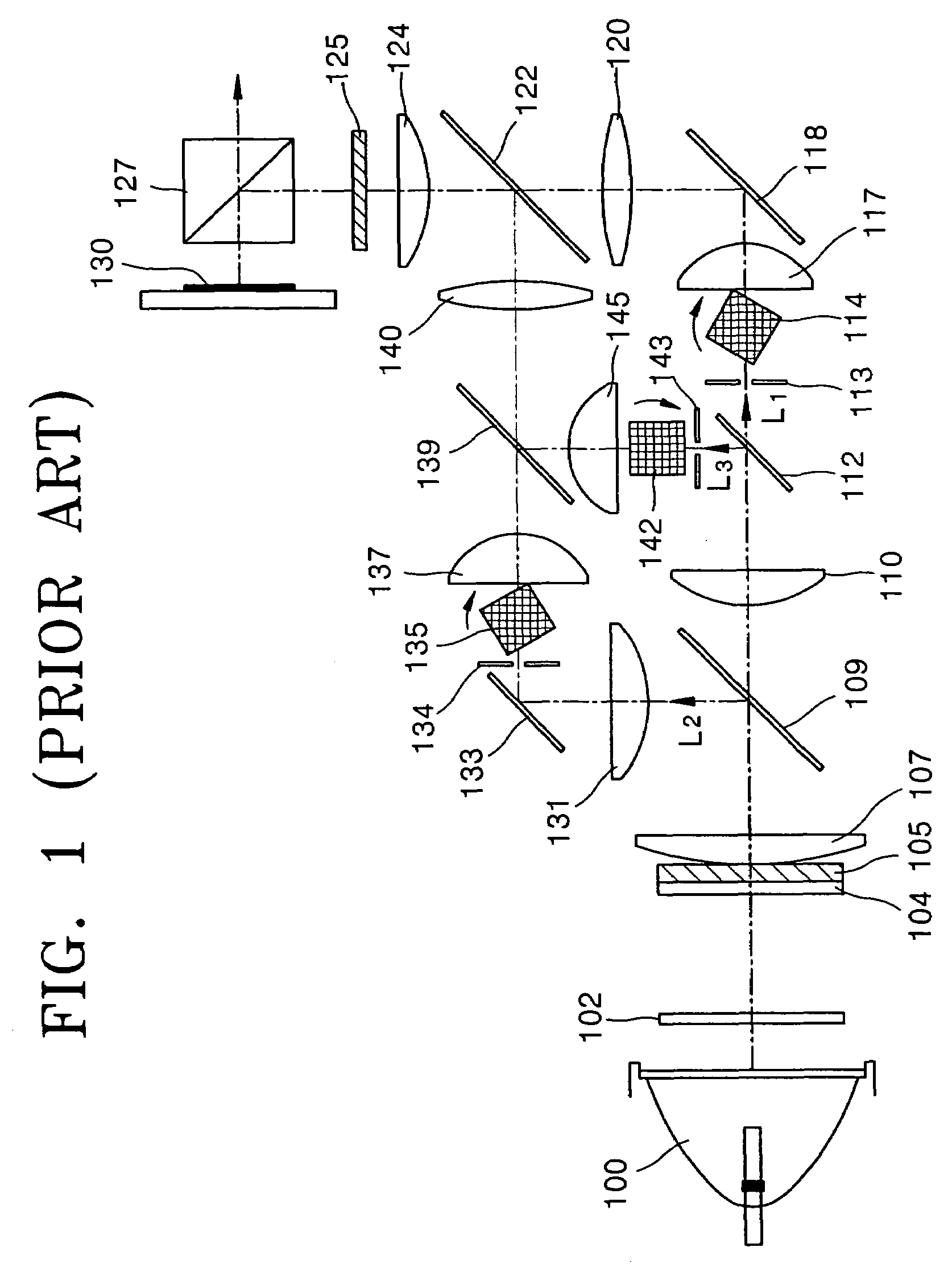
Hence, the conventional optical system is bulky, and the manufacturing and assembly thereof is complicated, thus degrading the yield.
Thus, the projection system adopting three motors is manufactured at a greater cost than a color wheel type projection system which utilizes a single motor.
However, controlling the synchronization is not easy.
Further, due to the individual circular motions of the first, second, and third prisms 114, 135, and 142, the color scrolling speed by the three scrolling prisms is irregular, consequently deteriorating the quality of the resultant image.

Method used


Image

  • Scrolling unit and projection system using the same
  • Scrolling unit and projection system using the same
  • Scrolling unit and projection system using the same

Examples


Embodiment Construction

[0051]Referring to FIG. 4, a scrolling unit 20 according to an embodiment of the present invention is formed by spirally arranging at least one lens cell 22 on an outer circumferential surface of a column-like plate 21. Preferably, but not necessarily, the lens cells 22 are cylinder lens cells. The column-like plate 21 may be of a drum shape or various polyprism shapes.

[0052]FIG. 5A is a side view of the scrolling unit 20, and FIG. 5B is a cross-section of an area of the scrolling unit 20 through which light L passes. The cross-section of the area of the scrolling unit 20 through which light L passes is shown as a cylinder lens array.

[0053]The scrolling unit 20 is rotatable. As shown in FIG. 5A, the rotation of the scrolling unit 20 simulates a rectilinear motion (which is in direction indicated by arrow B) of the cylinder lens cells 22 as viewed from an area A through which the light L passes. FIGS. 5A and 5B illustrate a process in which as viewed from light passing through the sc...


PUM


Abstract

A scrolling unit and a projection system using the same are provided. The scrolling unit is formed by spirally arranging on an outer circumferential surface of a column-like plate at least one lens cell which separates the incident light into a plurality of beams. As the scrolling unit rotates about a predetermined rotating axis, a lens array, defined by an area of the scrolling unit through which light passes, moves rectilinearly. Due to the use of the scrolling unit, a simple projection system can be obtained, and color scrolling is easily performed.

Description

[0001]This application claims the priority of Korean Patent Application No. 2003-33242, filed on May 24, 2003, in the Korean Intellectual Property Office, and the benefit of U.S. Patent Provisional Application No. 60 / 457,312, filed on Mar. 26, 2003, in U.S. Patent and Trademark Office, the disclosures of which are incorporated herein in their entirety by reference.BACKGROUND OF THE INVENTION[0002]1. Field of the Invention[0003]An apparatus consistent with the present invention relates to a scrolling unit and a projection system which forms a color image using the scrolling unit and, more particularly, to an endless track-like color scrolling unit which is installed on a single light path to handle all plural color beams and which can perform color scrolling upon rotation, and a projection system using the color scrolling unit.[0004]2. Description of the Related Art[0005]Projection systems are classified into either 3-panel projection systems or single-panel projection systems accord...

Claims


Application Information

Patent Timeline
Patent Type & Authority Patents(United States)
IPC IPC(8): G03B21/00G03B21/26G02B26/08G02B26/00H04N5/74G09G3/32H04N9/31
CPCH04N9/3197H04N9/3117H04N5/74
Inventor CHO, KUN-HOKIM, DAE-SIKKWON, SANG-CHUL
Owner SAMSUNG ELECTRONICS CO LTD
Why Eureka
Try Eureka