Automotive rear view mirror

a rear view mirror and automotive technology, applied in the direction of mirrors, instruments, vehicle components, etc., can solve the problems of distortion of the image generated by the mirror surface, unsatisfactory conventional flat surface rear view mirrors, etc., to achieve minimal multi-plane (fisheye) curvature, minimal distortion, and reduced size

Inactive Publication Date: 2006-02-21
LO KAM CHU
View PDF10 Cites 38 Cited by
  • Summary
  • Abstract
  • Description
  • Claims
  • Application Information

AI Technical Summary

Benefits of technology

[0006]The present invention relates to a rear view mirror having add-on mirror sections that have minimal multi-plane (fisheye) curvatures, whereby the enhanced image produced by the add-on mirror section has minimal distortion and size reduction.

Problems solved by technology

Conventional flat surface rear view mirrors are not completely satisfactory, in that flat surface mirrors cannot completely cover the areas that need to be covered, especially blind spots behind and alongside the rear corners of the vehicle.
One problem with fisheye mirrors is distortion of the image generated by the mirror surface.

Method used


Image

  • Automotive rear view mirror
  • Automotive rear view mirror
  • Automotive rear view mirror

Examples


Embodiment Construction

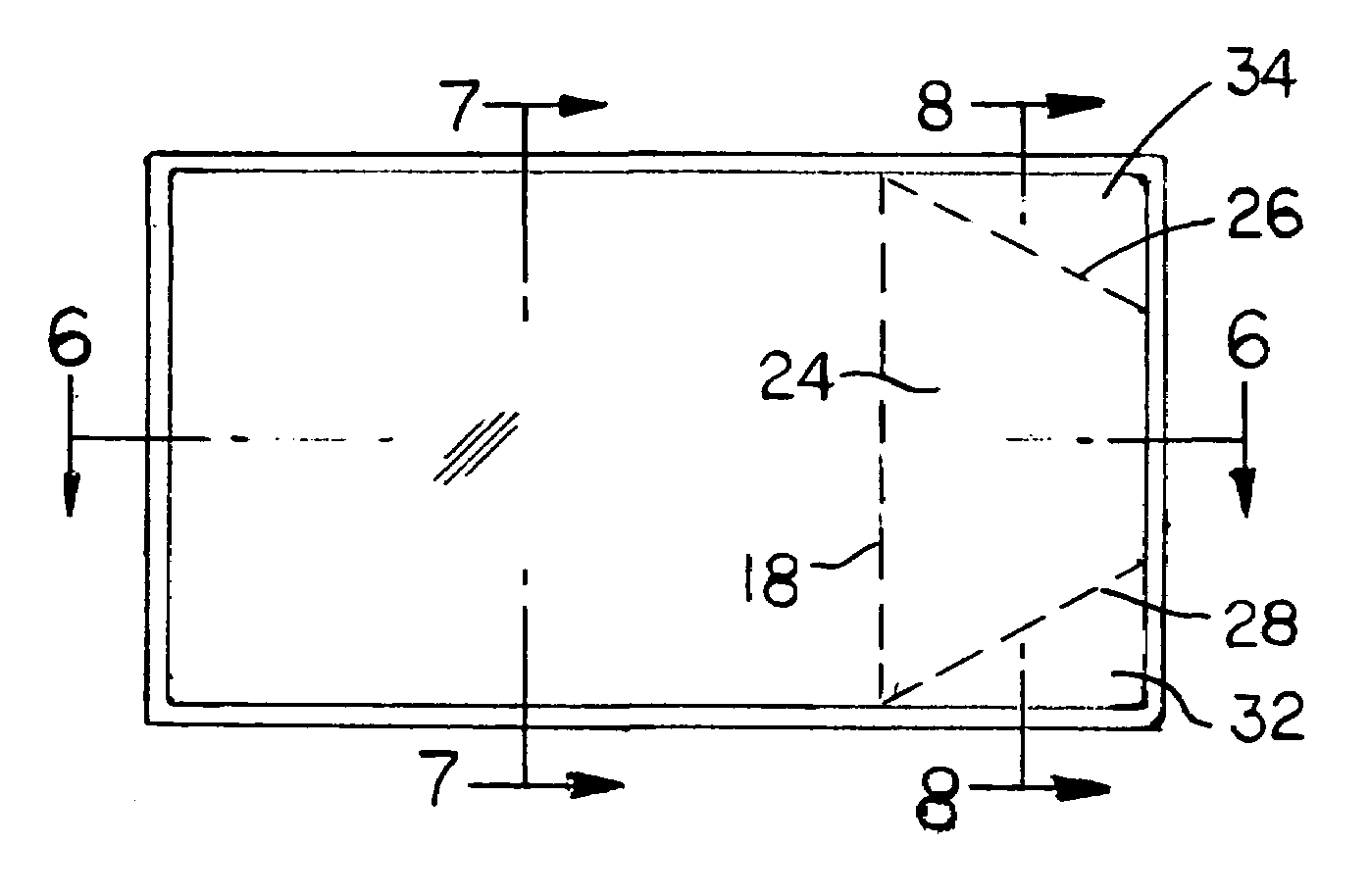
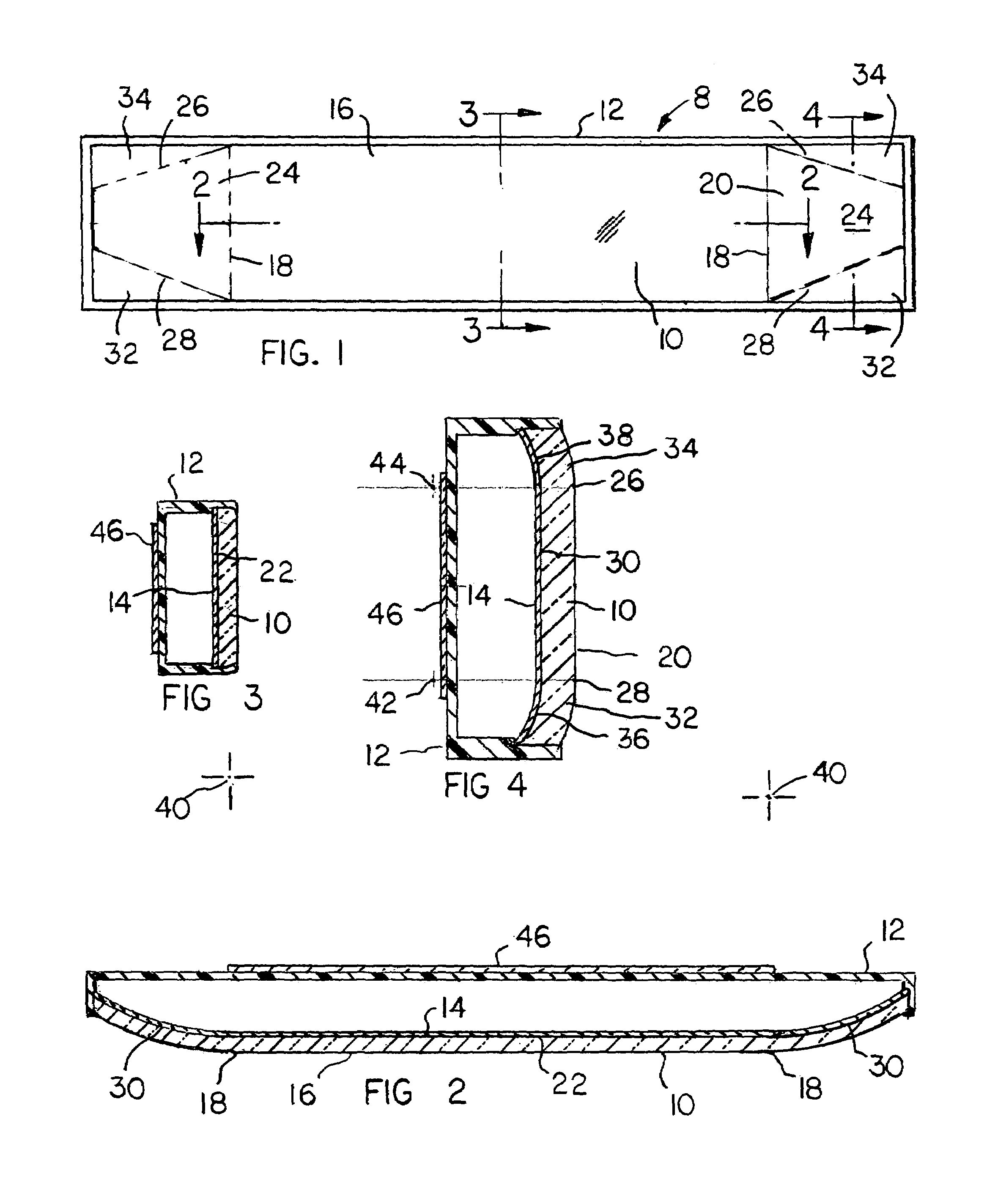
[0018]FIG. 1 is an eleavtional view of an automotive rear view mirror constructed according to the invention. The mirror shown in FIG. 1 is designed for positionment within a vehicle behind the front windshield on or near the longitudinal centerline of the vehicle. The mirror is often termed an interior rear view mirror because of its location within the vehicle.

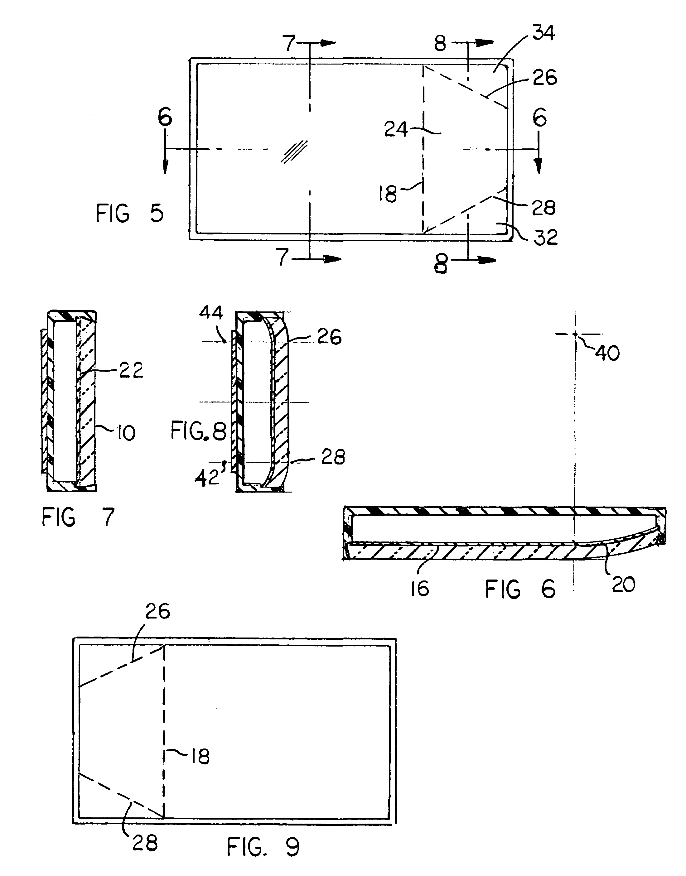
[0019]FIG. 5 is an elevational view of a second automotive rear view mirror embodying the invention. The FIG. 5 mirror is designed for positionment outside a vehicle on the passenger side of the vehicle; the mirror is attached to a front edge area of the vehicle door where it can be viewed by the driver of the vehicle. The FIG. 5 mirror is often termed an exterior rear view mirror.

[0020]FIG. 9 shows an exterior rear view mirror embodying the invention, and designed for positionment outside the vehicle on a front edge of the driver side door. FIGS. 1, 5 and 9 are taken in directions looking toward the mirror surface.

[0021]Ref...


PUM


Abstract

An automotive rear view mirror includes a primary flat reflective surface that generates an undistorted image, and three secondary reflective surfaces that are curved so as to increase the field of view laterally and also vertically. The curved reflective surfaces include a relatively large trapezoidal surface curved in the horizontal plane for increasing the field of view in the horizontal direction, and two smaller triangular curved reflective surfaces contiguous with the upper and lower boundaries of the trapezoidal surface for increasing the field of view in the vertical direction.

Description

FIELD OF THE INVENTION[0001]This invention relates to an automotive rear view mirror, and particularly to a rear view mirror having curved reflective surfaces for minimizing blind spots behind the vehicle on which the mirror is installed.BACKGROUND OF THE INVENTION[0002]Automotive vehicles are commonly equipped with rear view mirrors for enabling the driver to effectively view objects directly behind the vehicle or behind areas alongside the vehicle. Often the vehicle is equipped with an interior rear view mirror located behind the front windshield, and two exterior rear view mirrors mounted on the front doors of the vehicle.[0003]Conventional flat surface rear view mirrors are not completely satisfactory, in that flat surface mirrors cannot completely cover the areas that need to be covered, especially blind spots behind and alongside the rear corners of the vehicle.[0004]To minimize the undesired blind spots it has been proposed to incorporate curved convex reflective surfaces in ...

Claims


Application Information

Patent Timeline
Patent Type & Authority Patents(United States)
IPC IPC(8): G02B5/08B60R1/04B60R1/06B60R1/08
CPCB60R1/082
Inventor LO, KAM CHU
Owner LO KAM CHU
Why Eureka
Try Eureka