Method and device for calibrating an image sensor system in a motor vehicle

a technology of image sensor and motor vehicle, which is applied in the direction of image enhancement, process and machine control, instruments, etc., can solve the problems of measuring errors and not negligible, and achieve the effect of simple and exact possibility, great exactness in calibration

Active Publication Date: 2005-07-05
ROBERT BOSCH GMBH
View PDF4 Cites 32 Cited by
  • Summary
  • Abstract
  • Description
  • Claims
  • Application Information

AI Technical Summary

Benefits of technology

[0013]Advantageously, the alignment of a first and a second pointer, each having one pointer beam on a first and second non-steered wheel of the motor vehicle, together with the determination of at least one distance between the at least one calibrating object and the non-steered wheel may represent a simple and exact possibility of carrying out or performing the method described below. The advantages come about, on the one hand, by the use of only two pointers, which each generate only one pointer beam, and on the other hand, by the use of at least one distance. This leads to great exactness in the calibration of the at least one image sensor system. Furthermore, the use of at least one distance between the at least one calibrating object and the non-steered wheel, while carrying out the method, may advantageously permit a variable distance between the at least one calibrating object and the motor vehicle or the image sensor system.
[0014]Advantageously, the method and the device may be suitable for angles from 0° to 180° between the geometric travel axis and the calibrating object. This broad angle range may advantageously provide for the adaptation of the method and the device to the local place in the motor vehicle repair shop or on the production floor of motor vehicle manufacturer. Advantageously, the alignment of the calibrating object to the motor vehicle is such that the angle between the geometric travel axis and the calibrating object is close to perpendicular, and particularly amounts to exactly 90°. For example, during the alignment of the image sensor system in the direction of the geometric travel axis, that is, in the direction of the forward travel direction of the vehicle, or in the opposite direction, that is, in the direction backwards to the travel direction, this right-angled setting leads to great exactness in the calibration of the at least one image sensor system. Especially in response to the use of additional calibrating reference features on the calibrating object, an angle of approximately 90° leads to an increase in the accuracy of the calibration of the at least one image sensor system, because, on account of the perpendicular viewing angle of the image sensor system, distortions of the calibrating reference features become minimal.
[0015]Advantageously, the alignment of a first and a second pointer, each having one pointer beam on a first and second non-steered wheel of the motor vehicle, may represent a simple and accurate possibility of carrying out the method described below, since a precise alignment of the calibrating object to the motor vehicle may be omitted. Consequently, in a particularly advantageous manner, especially the determination of the position of the at least one image sensor system in the motor vehicle, and the determination of the alignment of the at least one image sensor system with respect to the geometric travel axis may be provided for.
[0016]In an especially advantageous manner, the method and the device described below may provide for the determination of the alignment of at least two image sensor systems to one another, the at least two image sensor systems photographing essentially the same scene. In particular, the method and the device described below may advantageously provide for the calibration of at least one stereo camera system with respect to the geometric travel axis of the motor vehicle.
[0017]Of advantage is the determination of at least one value of the intrinsic calibration data of the at least one image sensor system, which may be of the camera's principal point and / or the camera's principal distance and / or at least one distortion parameter and / or the determination of the influence of a glass pane in the light path of the at least one image sensor system. These intrinsic calibrating data may be advantageously determined at the same time, especially by the use of additional calibrating reference features. This saves time and costs, since this additional required calibration of the at least one image sensor system becomes unnecessary.
[0018]It may be particularly advantageous to use an electronic / optical range finder (distance measuring device) as pointer, since hereby there are carried out the determination of the distance between the at least one calibrating object and the non-steered wheel along at least one pointer beam, and the generation of a marking point by a single arrangement, the electronic / optical range finder. In particular, the latter's distance-measuring light beam may advantageously generate a light point as the marking point at the same time.

Problems solved by technology

There are deviations between the geometrical travel axis and the longitudinal axis, which, in a measuring image sensor system, especially when this is used in driver assistance systems, can lead to measuring errors, and are therefore not negligible.

Method used


Image

  • Method and device for calibrating an image sensor system in a motor vehicle
  • Method and device for calibrating an image sensor system in a motor vehicle
  • Method and device for calibrating an image sensor system in a motor vehicle

Examples


Embodiment Construction

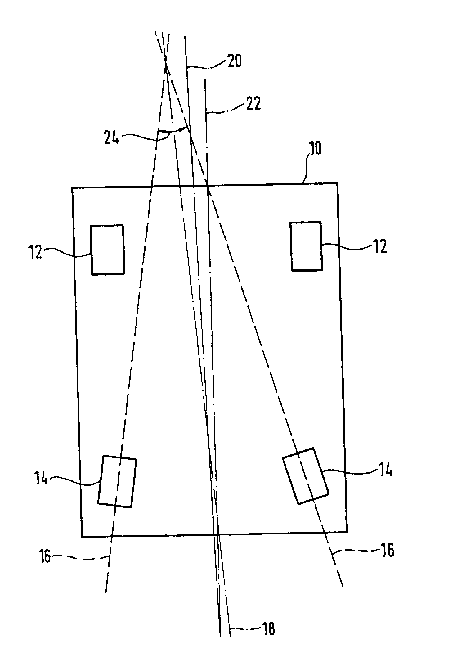
[0030]FIG. 1 shows a drawing to explain the definition of geometric travel axis 18, vehicle longitudinal central plane 20 and longitudinal axis 22 of a motor vehicle 10. What is shown is a motor vehicle 10 having the two steered front wheels 12 of the front axle and the two non-steered rear wheels 14 of the rear axle. The front axle and the rear axle are each one wheel axis (axle). Geometric travel axis 18 is defined as the bisector of total toe-in angle 24 of the rear axle, total toe-in angle 24 being fixed by track 16 of the two rear wheels 14 of the rear axle. Geometric travel axis 18 is parallel to the roadway plane. The roadway plane has not been drawn in FIG. 1.

[0031]By comparison to that, vehicle longitudinal central plane 20 is a plane which is located perpendicular to the roadway plane, and which goes through the middle of the track width of the front and rear axles. Longitudinal axis 22 may be projected by symmetrical features of motor vehicle 10, especially the vehicle bo...


PUM


Abstract

A method and a device for calibrating at least one image sensor system, which is located at (on and/or in and/or on top of) a motor vehicle, by the use of at least one calibrating object, for the calibration, and for determining the alignment of the at least one image sensor system with respect to the geometric travel axis of the motor vehicle.

Description

FIELD OF THE INVENTION[0001]The present invention relates to a method and a device for calibrating at least one image sensor system which is located on and / or in and / or on top of a motor vehicle, by the use of at least one calibrating object.BACKGROUND INFORMATION[0002]In motor vehicles, one thinks of the use of image sensor systems for recording the vehicle environment. In particular, the use of image sensor systems in driver assistance systems is planned. For example, image sensor systems may be used for the automatic regulation of the distance of the motor vehicle from a vehicle traveling ahead.[0003]To enlarge the image recording range, the use of several image sensor systems in the motor vehicle is planned, their recording ranges being able at least partially to overlap. In particular, the use of stereo cameras is provided that are made up of two image sensor systems, which photograph (take) essentially the same scene.[0004]Methods and devices are known for calibrating image se...

Claims


Application Information

Patent Timeline
Patent Type & Authority Patents(United States)
IPC IPC(8): G01D18/00
CPCG01D18/00G06T7/0018G06T2207/10012G06T2207/30208G06T2207/30252G06T7/80
Inventor UFFENKAMP, VOLKERABRAHAM, STEFFENSCHMACK, ANDREASEL-DIN, OMAR ALAA
Owner ROBERT BOSCH GMBH
Why Eureka
Try Eureka