Rotatable plug with an arcing resistant mechanism

a technology of arcing resistance and rotating plugs, which is applied in the direction of flexible/turnable line connectors, coupling device connections, coupling parts engagement/disengagement, etc., can solve the problem of more threatening the safety of users, and achieve the effect of long life and safe us

Inactive Publication Date: 2006-02-21
CHENG UEI PRECISION IND CO LTD
View PDF4 Cites 40 Cited by
  • Summary
  • Abstract
  • Description
  • Claims
  • Application Information

AI Technical Summary

Benefits of technology

[0009]As can be seen from the above description, a circuit exists between the prongs of the rotatable rack and the conductive terminals, so that the rotatable plug with an arcing resistant mechanism can suppress the arcing that is produced between the prongs of the rotatable rack and the conductive terminals, and thus the rotatable plug with an arcing resistant mechanism is used safely and has a long lifetime.

Problems solved by technology

As well known to all, the arcing terrifies users, and even more threatens the safety of the user.

Method used


Image

  • Rotatable plug with an arcing resistant mechanism
  • Rotatable plug with an arcing resistant mechanism
  • Rotatable plug with an arcing resistant mechanism

Examples


Embodiment Construction

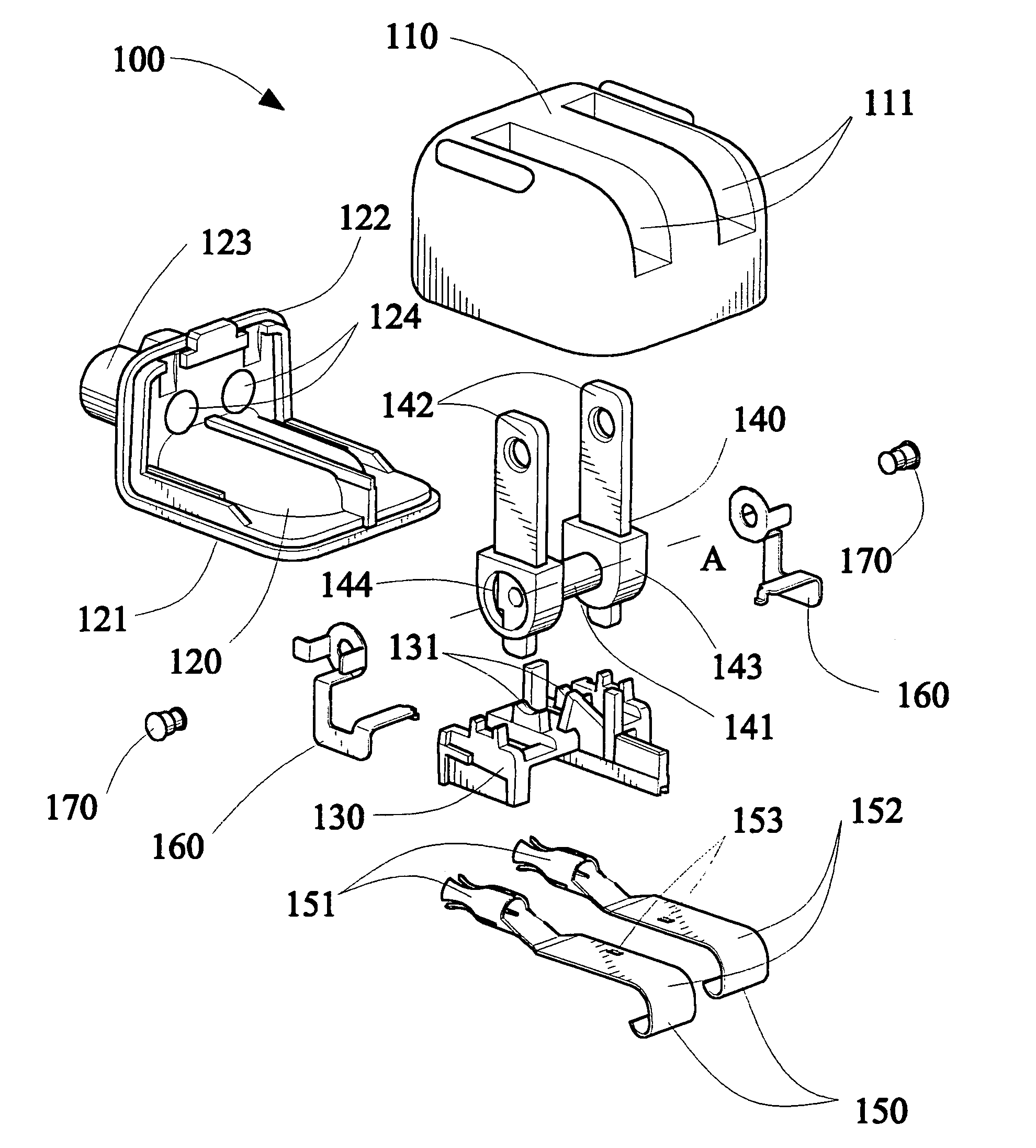
[0016]With reference to FIG. 1 and FIG. 2, a rotatable plug with an arcing resistant mechanism 100 is disclosed which includes an upper cover 110, a lower cover 120 mating with the upper cover 110 to form a holding space, a mount 130 placed on the lower cover 120 and held in the holding space, a rotatable rack 140 supported by the mount 130, a pair of conductive terminals 150 disposed on the lower cover 120, and a pair of connecting slices 160 which connect the rotatable rack 140 with the conductive terminals 150 respectively. There are two slots 111 defined on the top surface of the upper cover 110, and the two slots 111 are set in parallel along the transversal direction for the rotatable rack 140 to pass through and to be held therein.

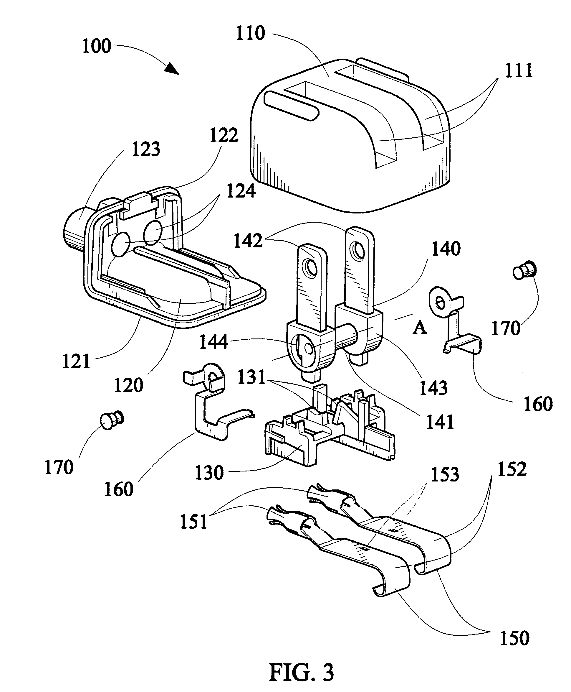
[0017]Along with reference to the FIG. 3, the lower cover 120 includes a base 121 and a vertical wall 122. The vertical wall 122 extends from the front side of the base 121. A protrusion 123 is extended from the outer surface of the vertical wall 12...


PUM


Abstract

A rotatable plug with an arcing resistant mechanism is disclosed which includes an upper cover, a lower cover mating with the upper cover to form a holding space, a mount placed in the holding space, a rotatable rack placed on the mount, a pair of conductive terminals fixed on the lower cover and a pair of connecting slices. The rotatable rack includes a pivot and a pair of prongs, wherein the prongs are fixed on the both ends of the pivot respectively. Each connecting slice connects the corresponding prong of the rotatable rack with the corresponding conductive terminal. Therefore a circuit exists between the prongs and the conductive terminals, so that the rotatable plug with an arcing resistant mechanism can suppress the arcing that is produced between the prongs and the conductive terminals. Thus the rotatable plug with an arcing resistant mechanism is used safely and has a long lifetime.

Description

BACKGROUND OF THE INVENTION[0001]1. Field of the Invention[0002]The present invention generally relates to a rotatable plug, and more particularly, to a rotatable plug with an arcing resistant mechanism.[0003]2. The Related Art[0004]With popularization of consumer electronics, various kinds of plugs, especially rotatable plugs come out. Due to their small size for carrying conveniently and beautiful appearance, the rotatable plugs are favored even more. With reference to FIG. 5, a rotatable plug is disclosed below according to prior art.[0005]The conventional rotatable plug 200 illustrated in FIG. 5 includes an upper cover 210, a lower cover 220, a mount 230 which is placed on the lower cover 220, a rotatable rack 240 placed on the mount 230 and a pair of conductive terminals 250 fixed on the lower cover 220 in juxtaposed relationship. A pair of slots 211 are formed longitudinally in parallel on the top surface of the upper cover 210. The upper cover 210 mates with the lower cover 2...

Claims


Application Information

Patent Timeline
Patent Type & Authority Patents(United States)
IPC IPC(8): H01R13/62
CPCH01R35/04
Inventor HUANG, TZU-HSUAN
Owner CHENG UEI PRECISION IND CO LTD
Why Eureka
Try Eureka