Vehicular turning indicator
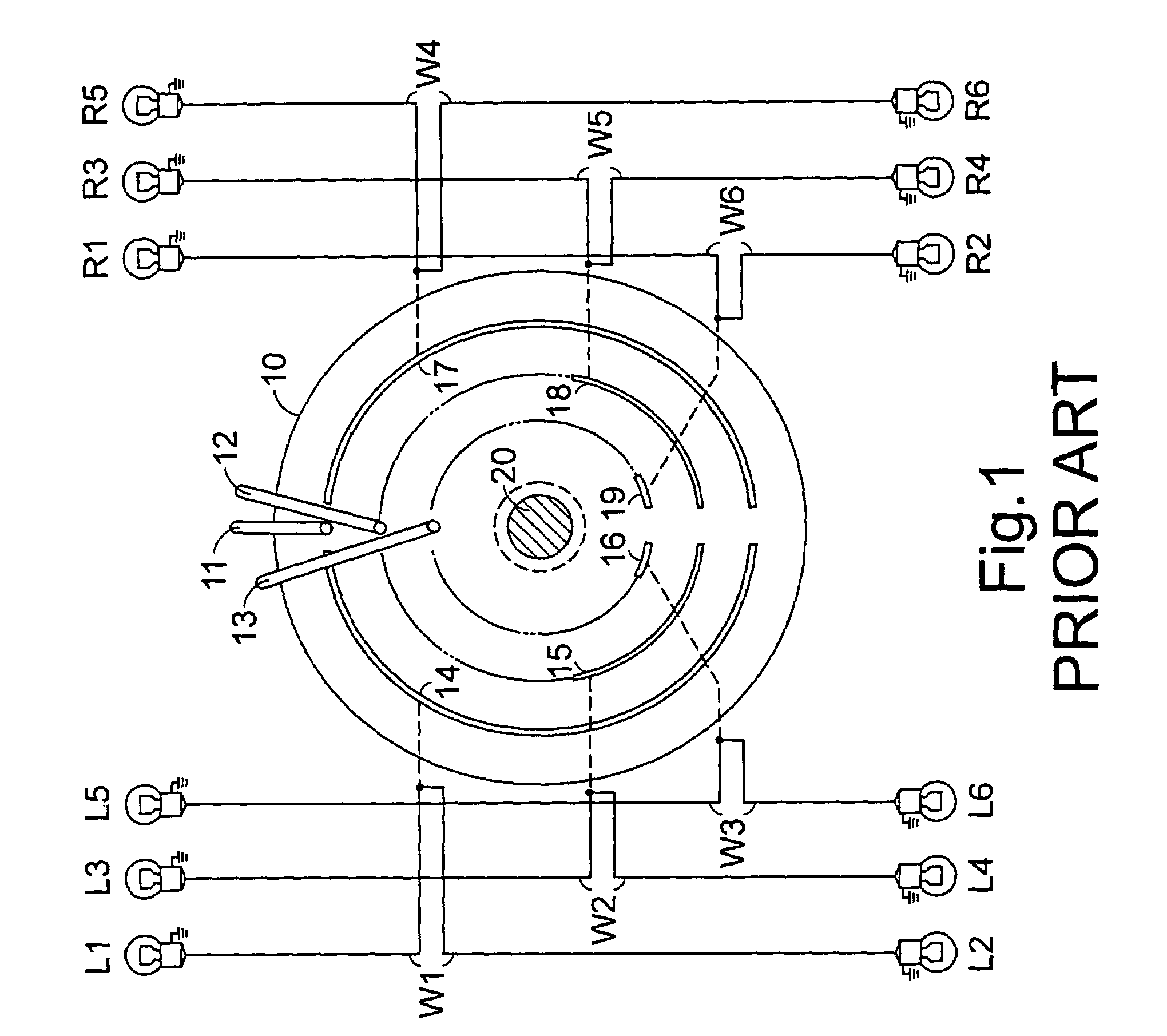
a turning indicator and turning technology, applied in the direction of vehicle components, signalling/lighting devices, optical signalling, etc., can solve the problems of complex circuitry, many car accidents, and limited
- Summary
- Abstract
- Description
- Claims
- Application Information
AI Technical Summary
Benefits of technology
Problems solved by technology
Method used
Image
Examples
first embodiment
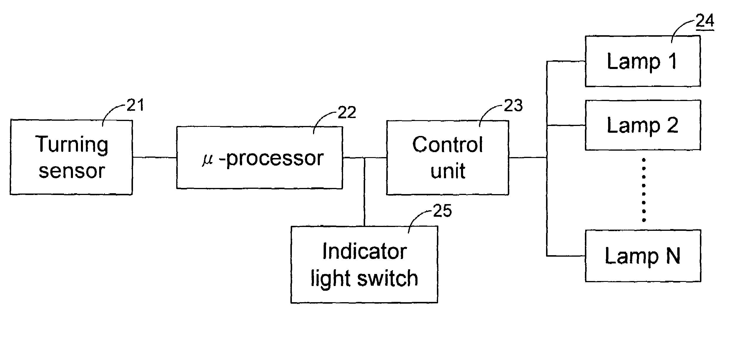
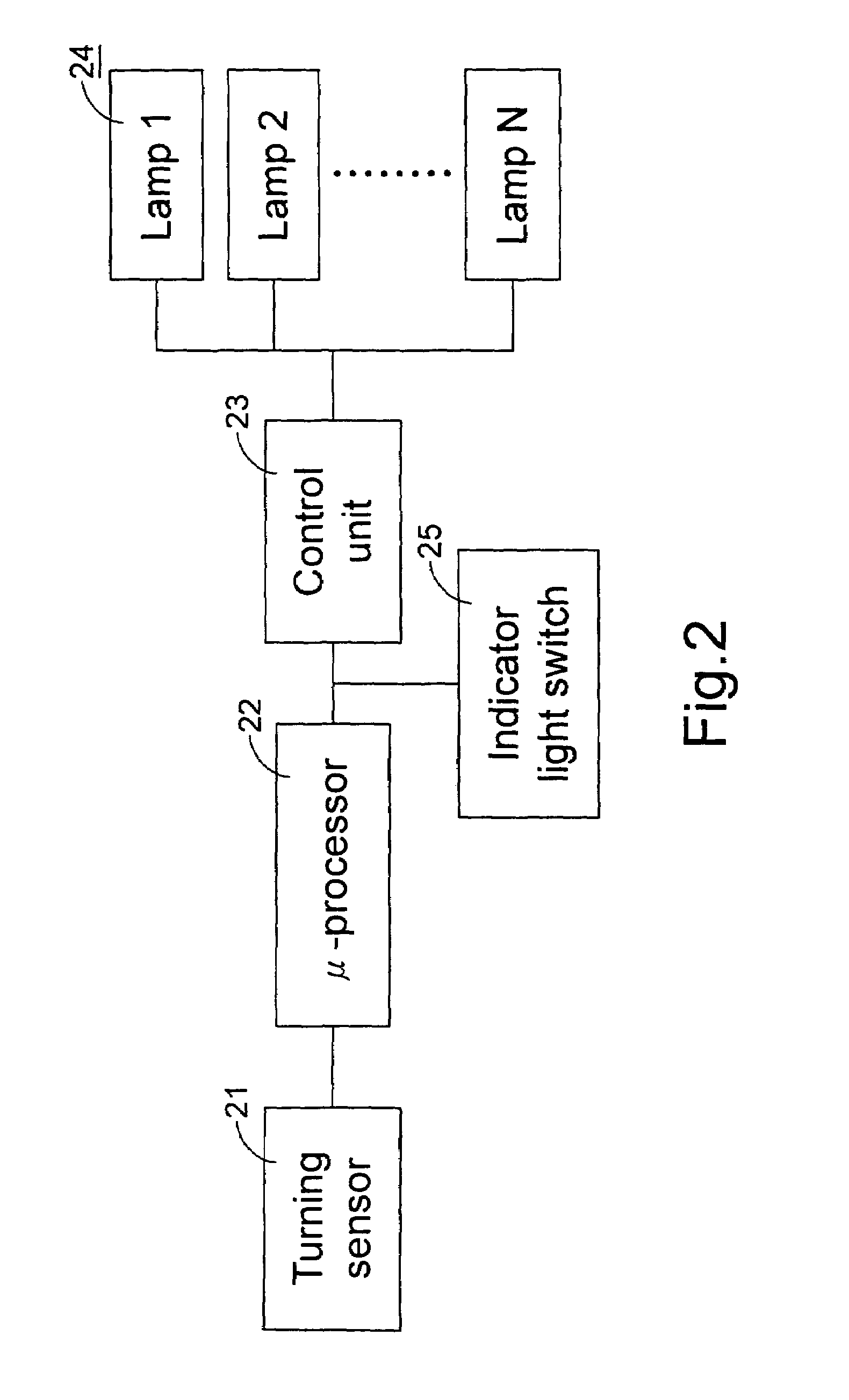
[0066]Please refer to FIG. 2 which shows the vehicular turning indicator according to the present invention. In this embodiment, the vehicular turning indicator is implemented by an indicator light, In other words, the vehicular turning indicator performs dual functions, one for direction indicator light and the other for dynamic turning indication light. In the former case, the vehicular turning indicator is enabled in a constant pattern to show that the vehicle is going to take a turn in response to an ON state of an indicator light switch. In the latter case, the vehicular turning indicator is enabled in a variable pattern to show that the vehicle is now turning and show the turning degree of the vehicle as well.
[0067]The vehicular turning indicator shown in FIG. 2 includes a turning sensor 21, a micro-processor 22, a control unit 23 and a series of lightening units known together as lamps 24 intercommunicated as shown. The control unit 23 is further in communication with the ind...
second embodiment
[0075]Please refer to FIG. 6 which shows the vehicular turning indicator according to the present invention. In this embodiment, the vehicular turning indicator is implemented by a brake light. In other words, the vehicular turning indicator performs dual functions, one for brake indication and the other for dynamic turning indication. In the former case, the vehicular turning indicator is enabled in a constant pattern to show that the vehicle is braking. In the latter case, the vehicular turning indicator is enabled in a variable pattern to show that the vehicle is now turning and show the turning degree of the vehicle as well.
[0076]The vehicular turning indicator shown in FIG. 6 includes a turning sensor 61, a micro-processor 62, a control unit 63 and a series of lamps 64 intercommunicated as shown. The control unit 23 is further in communication with a brake sensor 65. It is to be noted that the connecting lines among these devices as shown do not indicate the connection of these...
third embodiment
[0081]Please refer to FIG. 9 which shows the vehicular turning indicator according to the present invention. In this embodiment, the vehicular turning indicator is incorporated into a head-up display, which is generally projected on the front windscreen of the vehicle. The vehicular turning indicator shown in FIG. 9 includes a turning sensor 91, a micro-processor 92, a control unit 93 and a series of light-emitting elements 94 intercommunicated as shown. The control unit 93 is optionally in communication with an information input device 95. It is to be noted that the connecting lines among these devices as shown do not indicate the connection of these devices essentially by wires or cables. Alternatively, they can communicate with one another via a vehicular digital bus such as a controller area network (CAN) or vehicle area network (VAN) bus. The sensor 91, like the sensor 21, can be a 9850 Gen II Series sensor or an NCAPS® Thin Profile sensor, which is mounted to a steering wheel ...
PUM
 Abstract
Description
Claims
Application Information
 - R&D
- Intellectual Property
- Life Sciences
- Materials
- Tech Scout
- Unparalleled Data Quality
- Higher Quality Content
- 60% Fewer Hallucinations
Browse by: Latest US Patents, China's latest patents, Technical Efficacy Thesaurus, Application Domain, Technology Topic, Popular Technical Reports.
© 2025 PatSnap. All rights reserved.Legal|Privacy policy|Modern Slavery Act Transparency Statement|Sitemap|About US| Contact US: help@patsnap.com


