Numeral lock housing structure

a numeral lock and housing technology, applied in padlocks, building locks, constructions, etc., can solve the problems of poor strength and reliability of the numeral lock as a whole, greatly limited turning angle and prone to collision and damage of the numeral wheel b>10/b>, etc., to achieve the effect of improving the numeral lock

Inactive Publication Date: 2005-04-19
YU CHUN TE
View PDF16 Cites 42 Cited by
  • Summary
  • Abstract
  • Description
  • Claims
  • Application Information

AI Technical Summary

Benefits of technology

[0005]It is therefore a primary object of the present invention to provide an improved numeral lock housing structure including a lock housing composed of two halves mated with each other. Each of the halves is formed with at least one lateral face and a front face forward extending from the lateral face. A corner section between the lateral face and the front face of at least one of the two halves is formed with at least one numeral wheel window. The numeral wheel window extends into the front face without crossing the mating edge thereof. Therefore, the mating edges of the two halves of the lock housing will not be interrupted so that the structure of the front face of the lock housing is kept integrated.
[0006]It is a further object of the present invention to provide the above numeral lock housing structure in which the numeral wheel window is bridged between the lateral face and the front face of the lock housing so that the numeral wheel is positioned between the lateral face and the front face. Therefore, the numeral wheel has larger turning angle each time the numeral wheel is turned so that the operation of the numeral lock is facilitated.

Problems solved by technology

Therefore, the numeral wheel has greatly limited turning angle each time the numeral wheel is turned.
This is quite inconvenient.
In addition, the numeral wheels 10 are apt to be collided and damaged.
As a result, the strength and reliability of the numeral lock as a whole are poor.

Method used


Image

  • Numeral lock housing structure
  • Numeral lock housing structure
  • Numeral lock housing structure

Examples


Embodiment Construction

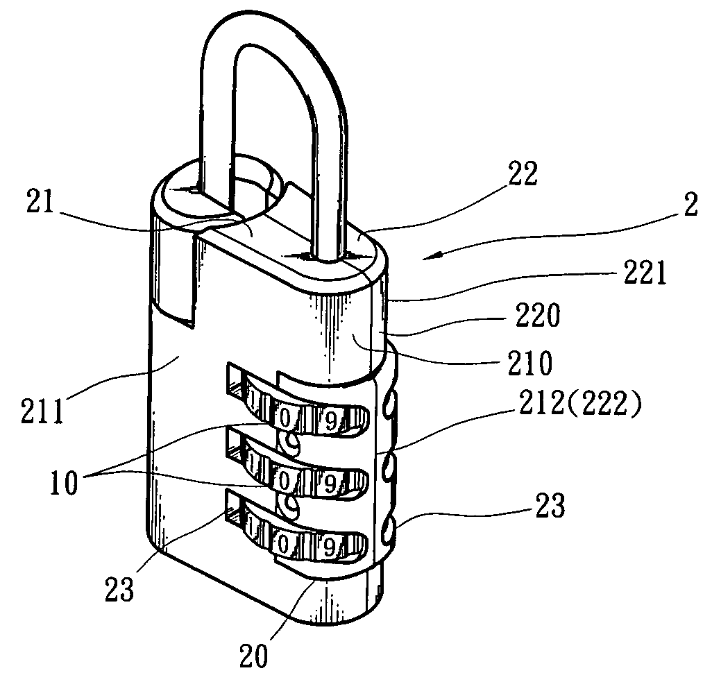
[0017]Please refer to FIGS. 4, 4A and 5. The present invention includes a lock housing 2 composed of two halves 21, 22 mated with each other. Each half 21, 22 is formed with at least one lateral face 211, 221 and a front face 210, 220 forward extending from the lateral face. Two edges 212, 222 of the front faces 210, 220 form two mating edges 212, 222 mated with each other.

[0018]A corner section 20 between the lateral face 211, 221 and the front face 210, 220 of at least one of the two halves 21, 22 is formed with at least one numeral wheel window 23. At least one numeral wheel 4 is mounted in the numeral wheel window 23 for driving a lock bolt 3 disposed in the lock housing 2. The numeral wheel 4 can be turned from outer side of the lock housing 2 to drive the lock bolt 3. The lock bolt 3 controls a locking / unlocking unit to lock or unlock the numeral lock.

[0019]The numeral wheel window 23 is bridged between the lateral face 211, 221 and the front face 210, 220. In addition, the n...


PUM


Abstract

A numeral lock housing structure including a lock housing composed of two halves mated with each other. Each of the halves is formed with at least one lateral face and a front face forward extending from the lateral face. Two edges of the front faces form two mating edges mated with each other. A corner section between the lateral face and the front face of at least one of the two halves is formed with at least one numeral wheel window. At least one numeral wheel is mounted in the numeral wheel window for controlling a lock bolt to lock / unlock the numeral lock. The numeral wheel window extends into the front face without crossing the mating edge thereof. Therefore, the mating edges of the two halves of the lock housing will not be slotted so that the structure of the front face of the lock housing is kept integrated. The numeral wheel is positioned between the lateral face and front face so that the numeral wheel has larger turning angle each time the numeral wheel is turned.

Description

BACKGROUND OF THE INVENTION[0001]The present invention is related to an improved numeral lock housing structure in which the numeral wheel window is re-designed and formed between the lateral face and front face of the lock housing. The numeral wheel window extends into the front face without crossing the mating edge thereof. Therefore, the mating edges of the two halves of the lock housing will not be slotted so that the structure of the front face of the lock housing is kept integrated. In addition, the numeral wheel is positioned in the corner between the lateral face and front face so that the numeral wheel has larger turning angle each time the numeral wheel is turned.[0002]FIG. 1 shows a conventional numeral lock. Several numeral wheel windows 13 are formed on a lateral face 12 of the lock housing 11. Several numeral wheels 10 are disposed in the windows 13. The mating edges 15 of the front faces of the lock housing 11 are not interrupted by the windows 13. Therefore, the fron...

Claims


Application Information

Patent Timeline
Patent Type & Authority Patents(United States)
IPC IPC(8): E05B37/02E05B37/06E05B37/00
CPCE05B37/025Y10T70/424Y10T70/426Y10T70/435Y10T70/489Y10T70/7305
Inventor YU, CHUN-TE
Owner YU CHUN TE
Why Eureka
Try Eureka