

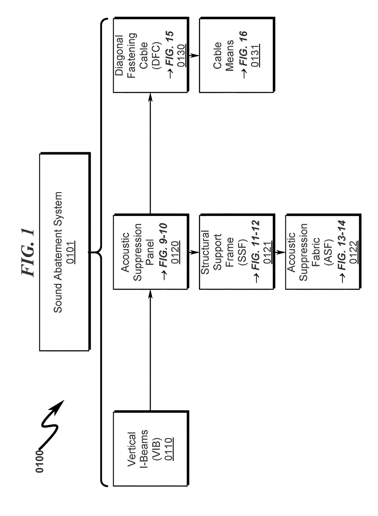
Sound abatement system and method
a sound abatement system and sound abatement wall technology, applied in the direction of fastening means, rod connections, mechanical equipment, etc., can solve the problems of high noise generated by oil and gas exploration and extraction operations, material may be more prone to deterioration, and noise generated by oil and gas operations is generally considered undesirable, so as to promote the overall structural integrity of the sound abatement system and facilitate shipment.
- Summary
- Abstract
- Description
- Claims
- Application Information
AI Technical Summary
Benefits of technology
Problems solved by technology
Method used
Image

Examples
embodiment (
Exemplary Binding Retention Plate Embodiment (1700)-(2000)
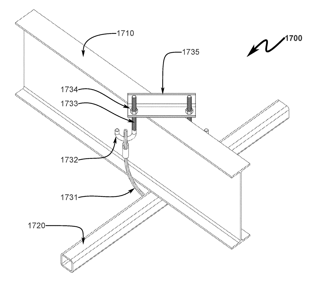
[0138]A preferred exemplary invention employing a binding retention plate (BRP) is depicted in FIG. 17 (1700)-FIG. 20 (2000). In this preferred embodiment, the diagonal fastening cable (DFC) means is implemented utilizing a looped cable (1731) in conjunction with J-hooks (1732) having a threaded fastening shaft (1733), fasteners (1734), and a binding retention plate (BRP) (1735) typically constructed of angle iron. This configuration permits the VIB (1710) to be frictionally mated to the SSF (1720) by tightening the fasteners (1734) to place a predetermined tension on the looped cable (1731).
[0139]Inspection of this diagram illustrates several of the advantages of the present invention over the prior art. Specifically, the web length of the VIB (1710) may be quite large with respect to the cross sectional dimensions of the SSF (1720) as depicted in this scaled example illustrating a typical 12-inch VIB and 2×2 SSF tubular ste...
PUM
 Abstract
Description
Claims
Application Information