Pipeline dredging system

A technology for pipelines and water pipes, applied in the field of pipeline dredging systems, can solve problems such as difficult dredging, and achieve the effects of improving dredging effect, improving dredging efficiency and high flexibility

Active Publication Date: 2020-11-13
宏腾建设集团有限公司
View PDF7 Cites 5 Cited by
  • Summary
  • Abstract
  • Description
  • Claims
  • Application Information

AI Technical Summary

Problems solved by technology

[0003] In the existing technology, high-pressure water guns are used to directly clean the pipelines, but this method is only suitable for loose deposits. If the deposits are dense, a large amount of clean water is required for continuous flushing, which makes dredging more difficult.

Method used


Image

  • Pipeline dredging system
  • Pipeline dredging system
  • Pipeline dredging system

Examples


Embodiment Construction

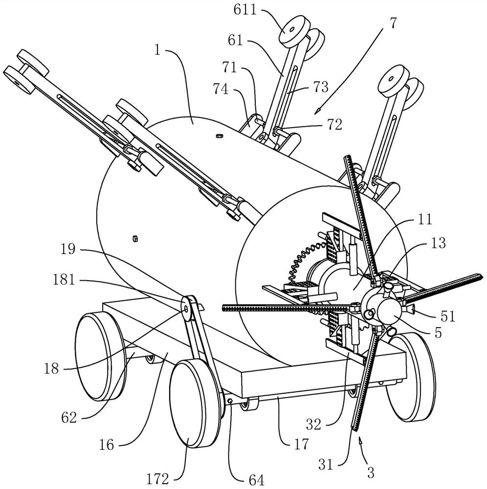
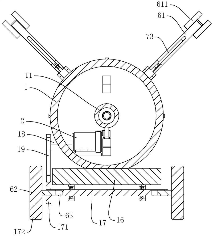
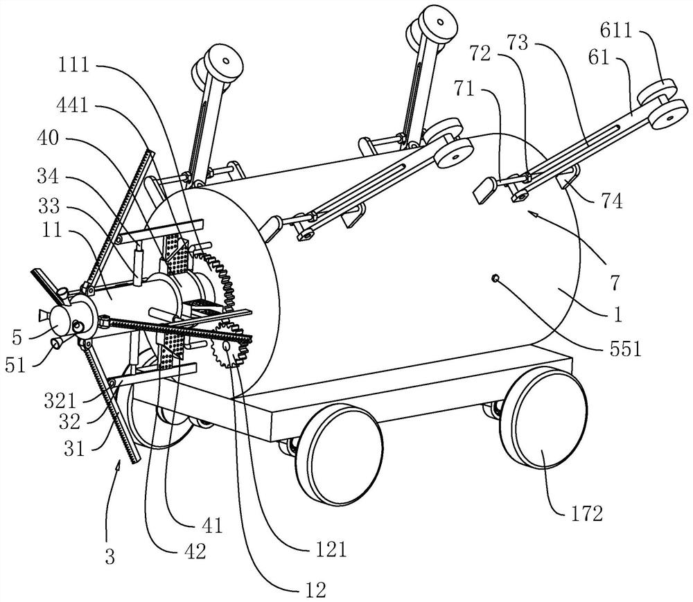
[0038] The following is attached Figure 1-5 The application is described in further detail.

[0039] The embodiment of the present application discloses a pipeline dredging system. Such as figure 1 with figure 2 The dredging system includes a drill barrel 1, the outer wall of the drill barrel 1 is provided with a chassis 16, the outer wall of the drill barrel 1 is provided with a chassis 16, and the side of the chassis 16 away from the drill barrel 1 is rotationally connected with two parallel rotating shafts 17, and the axis of the rotating shaft 17 is Perpendicular to the axis of the drill barrel 1, both ends of each rotating shaft 17 are provided with telescopic grooves 63 extending axially, each telescopic groove 63 is inserted with a telescopic column 62, and the telescopic column 62 is located outside the rotating shaft 17. One end is coaxially provided with a walking wheel 172, and the rotating shaft 17 is threadedly connected with an adjusting screw 64, and the en...


PUM


Abstract

The invention relates to a pipeline dredging system which is applied to the technical field of pipeline dredging. The system comprises a drilling barrel, wherein a mandrel is rotationally connected tothe end of the drilling barrel, a plurality of scrapers are arranged on the mandrel in the circumferential direction, a driven gear is arranged at the end, close to the drilling barrel, of the mandrel, a driving motor is arranged in the drilling barrel, a motor shaft of the driving motor penetrates out of the drilling barrel, a driving gear meshed with the driven gear is arranged at the end, penetrating out of the drilling barrel, of the motor shaft of the driving motor, one end of the mandrel extends into the drilling barrel, a through groove which is through in the axial direction of the mandrel is formed in the mandrel, a sealing bearing is arranged at the end, located in the drilling barrel, of the groove wall of the through groove, and a water conveying pipe is arranged on the innerring of the sealing bearing. The pipeline dredging system has the effect of reducing the pipeline dredging difficulty.

Description

technical field [0001] The present application relates to the field of pipeline dredging technology, in particular to a pipeline dredging system. Background technique [0002] Urban rainwater, water supply, sewage and other drainage pipes, as the main municipal facilities of the city, are prone to deposit sediment, sand and other debris inside the pipes after long-term operation and use, which will greatly affect the water delivery flow of the pipes. Therefore, regular maintenance is required. The inside of the pipeline is dredged. [0003] In the existing technology, high-pressure water guns are used to directly clean the pipelines, but this method is only suitable for loose deposits. If the deposits are dense, a large amount of clean water is required for continuous flushing, which makes dredging more difficult. . Contents of the invention [0004] In order to reduce the difficulty of pipeline dredging, the present application provides a pipeline dredging system. [0...

Claims


Application Information

Patent Timeline
Patent Type & Authority Applications(China)
IPC IPC(8): E03F9/00
CPCE03F9/00E03F9/005
Inventor 王文倪胜丁宏伟徐卫东徐盛黄强
Owner 宏腾建设集团有限公司
Why Eureka
Try Eureka