

Wharf bottom desilting machine and method
A wharf and machine tool technology, applied in the wharf field, can solve problems such as low return on investment, low work efficiency, and high price
- Summary
- Abstract
- Description
- Claims
- Application Information
AI Technical Summary
Problems solved by technology
Method used
Image

Examples
Embodiment 1
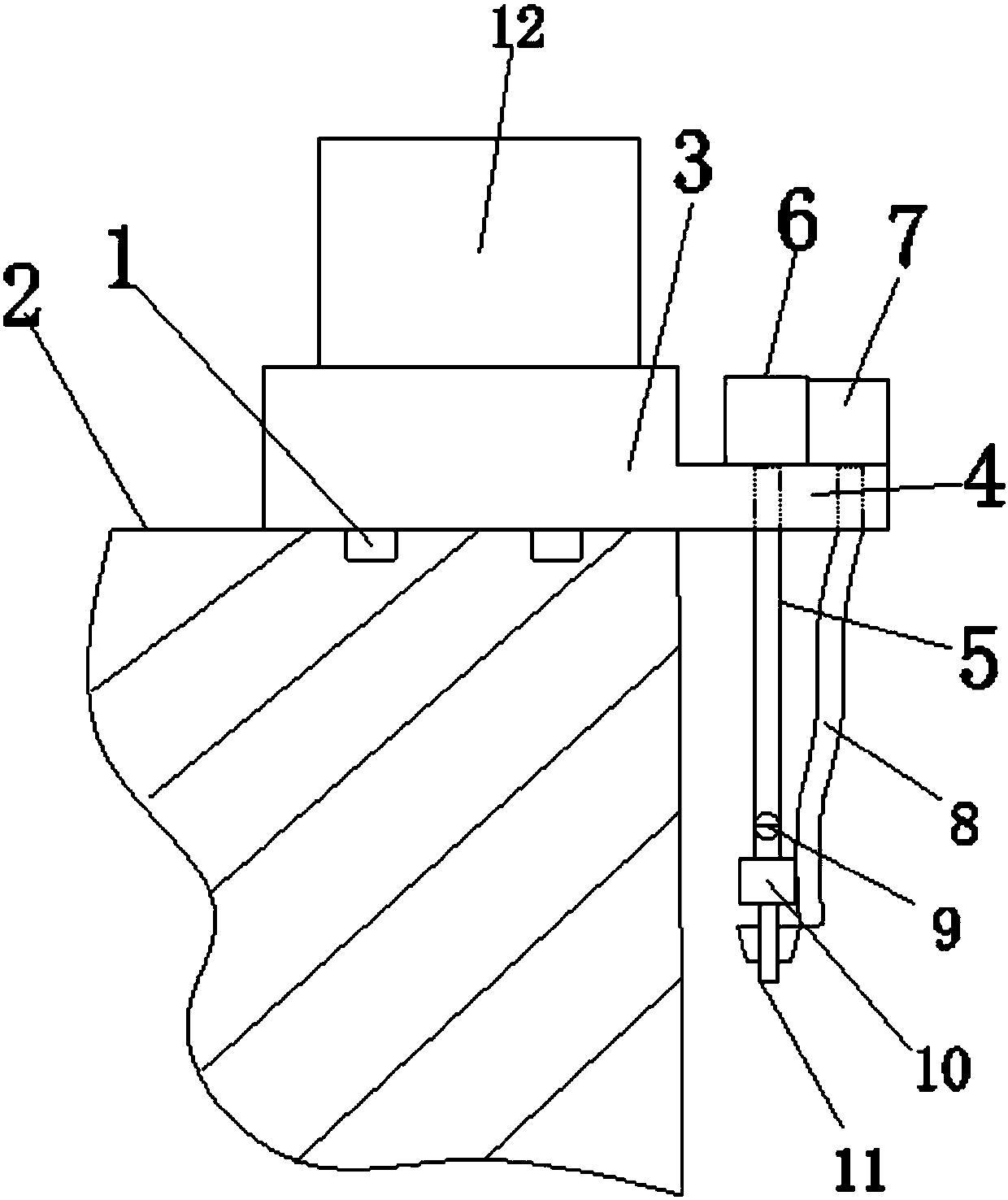
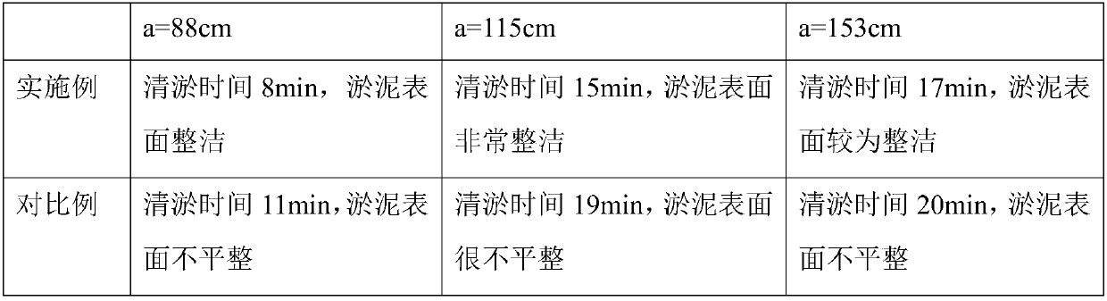
[0045]Embodiment 1 obtains the silt height c of 88cm at the position to be dredged, which is the difference between a and b, which is 38cm, and calculates the volume v of the silt to be removed according to the silt height, and v equals the work of the dredging parts The product of area s and c, s is 1m 2 , then v is 0.38m 3 , move the support platform to the position to be dredged through the cooperation of the slide rail and the chute, and fix it;
[0046] When the hydraulic cylinder is turned on, the dredging parts will drop by 88cm driven by the telescopic rod; when the hydraulic cylinder is turned off, the dredging parts will stop falling;
[0047] Turn on the motor, the agitating fins start to rotate, and at the same time turn on the high-pressure water pump, the water flow is sprayed out through the water pipe and the nozzle, after a predetermined lag time, the mud pump is turned on, and the sludge enters the mud storage tank through the mud delivery pipe;
[0048] Th...
Embodiment 2
[0052] Obtain the silt height c of 115cm at the position to be dredged, which is the difference between a and b, which is 65cm, and calculate the volume v of the silt to be removed according to the silt height, and v is equal to the working area s and The product of c, s is 1m 2 , then v is 0.65m 3 , move the support platform to the position to be dredged through the cooperation of the slide rail and the chute, and fix it;
[0053] When the hydraulic cylinder is turned on, the dredging part will drop 115cm under the drive of the telescopic rod; when the hydraulic cylinder is turned off, the dredging part will stop falling;
[0054] Turn on the motor, the agitating fins start to rotate, and at the same time turn on the high-pressure water pump, the water flow is sprayed out through the water pipe and the nozzle, after a predetermined lag time, the mud pump is turned on, and the sludge enters the mud storage tank through the mud delivery pipe;
[0055] The hydraulic cylinder i...
Embodiment 3
[0059] Obtain the silt height c of 153cm at the position to be dredged, which is the difference between a and b, which is 103cm, and calculate the volume v of the silt to be removed according to the silt height, and v is equal to the working area s and The product of c, s is 1m 2 , then v is 1.03m 3 , move the support platform to the position to be dredged through the cooperation of the slide rail and the chute, and fix it;
[0060] When the hydraulic cylinder is turned on, the dredging parts will drop 153cm under the drive of the telescopic rod, and when the hydraulic cylinder is turned off, the dredging parts will stop falling;
[0061] Turn on the motor, the agitating fins start to rotate, and at the same time turn on the high-pressure water pump, the water flow is sprayed out through the water pipe and the nozzle, after a predetermined lag time, the mud pump is turned on, and the sludge enters the mud storage tank through the mud delivery pipe;
[0062] The hydraulic cyl...
PUM
 Abstract
Description
Claims
Application Information