Water conservancy project water supply and drainage pipeline internal wall dredging device

A water conservancy project and desilting device technology, which is applied to water supply devices, cleaning sewer pipes, waterway systems, etc., can solve the problems of time-consuming and laborious cleaning, low cleaning efficiency, and short distance of manual cleaning, etc., to improve the desilting effect and structure Reasonable design, the effect of improving dredging efficiency

Active Publication Date: 2020-07-28
山东水利职业学院
View PDF7 Cites 8 Cited by
  • Summary
  • Abstract
  • Description
  • Claims
  • Application Information

AI Technical Summary

Problems solved by technology

[0004] During the use of water supply and drainage pipelines in water conservancy projects, after a period of use, some sediments will be generated in the pipelines, and the sediments need to be dredged to prevent the sediments from clogging the pipelines and affecting the normal use of the pipelines
When cleaning water conservancy pipelines, most of them use manual cleaning methods, using brushes to clean the inner wall of the pipeline, the cleaning efficiency is low, the distance of manual cleaning is short, and after the cleaning is completed, it is necessary to use water pipes to clean the inner wall of the pipeline. Cleaning the inside of the pipeline is time-consuming and labor-intensive, and the cleaning efficiency is low. Therefore, we propose a dredging device for the inner wall of water supply and drainage pipelines in water conservancy projects

Method used


Image

  • Water conservancy project water supply and drainage pipeline internal wall dredging device
  • Water conservancy project water supply and drainage pipeline internal wall dredging device
  • Water conservancy project water supply and drainage pipeline internal wall dredging device

Examples


Embodiment 1

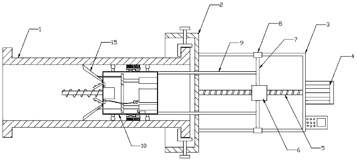
[0024] see Figure 1-5 As shown, this embodiment is a dredging device for the inner wall of water supply and drainage pipes in water conservancy projects, including a pipe 1 and a mounting seat 2, a U-shaped frame 3 is connected to the right side wall of the mounting seat 2, and a second U-shaped frame is connected to the right end of the U-shaped frame 3. A motor 4, the left output end of the first motor 4 is connected with a screw rod 5, the outer wall of the screw rod 5 is screwed with a nut seat 6, the upper and lower ends of the nut seat 6 are symmetrically connected with a fixed rod 7, and the end of the fixed rod 7 is connected There is a guide sleeve 8, the guide sleeve 8 is movably set on the transverse end of the U-shaped frame 3, the middle part of the left end of the fixed rod 7 is connected with a horizontal strut 9, the horizontal strut 9 runs through the mounting seat 2, and the horizontal strut 9 extends into the pipe 1 One end of the inner cavity is connected ...

Embodiment 2

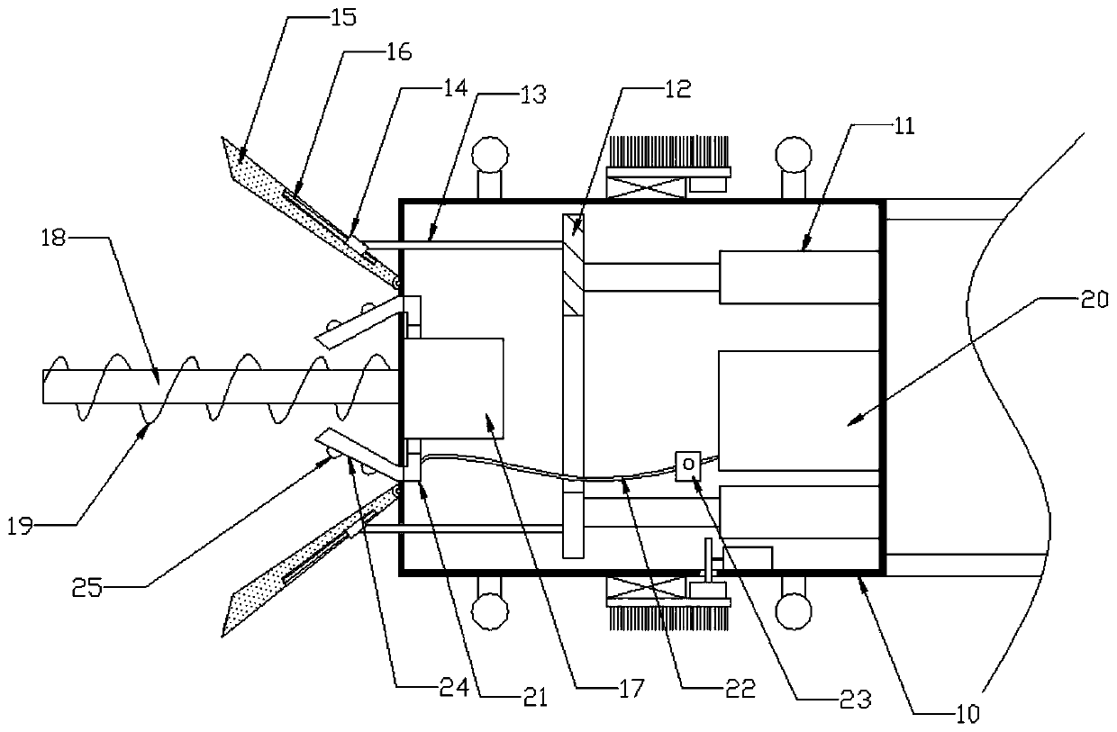
[0030] On the basis of Embodiment 1, a water tank 20 is connected to the middle part of the inner cavity right wall of the dredging housing 10, and an annular water pipe 21 is connected to the left wall of the inner cavity of the dredging housing 10, and the water tank 20 and the annular water pipe 21 are connected with a Water delivery pipe 22, water pump 23 is installed on the water delivery pipe 22, the left end of annular water pipe 21 is connected with inclined pipe 24 symmetrically up and down, and the outer wall of inclined pipe 24 is equipped with shower nozzle 25.

[0031] In this embodiment, the clear water is stored in the water tank 20, and the clear water in the water tank 20 can be extracted and pressurized by the water pump 23. The clear water enters the annular water pipe 21 along the water delivery pipe 22, and then extends out of the dredging housing 10 from the inclined pipe 24. Spraying through the nozzle 25 can flush the removed impurities, so as to facilit...

Embodiment 3

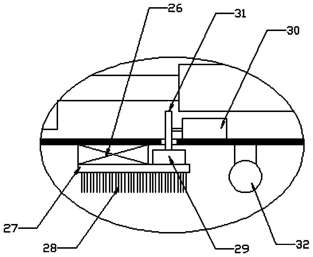
[0033] On the basis of Embodiment 1, the middle part of the outer wall of the dredging housing 10 is connected with a bearing ring 26, the outer wall of the bearing ring 26 is connected with an annular block 27, the outer wall of the annular block 27 is connected with a cleaning brush 28, and the inner wall of the annular block 27 is right The side is connected with the ring rack 29, and the inner cavity bottom of the dredging housing 10 is connected with the third motor 30, and the output end of the third motor 30 is connected with the transmission gear 31, and the transmission gear 31 lower end meshes with the ring rack 29.

[0034] The bottom of the dredging housing 10 is provided with a notch matched with the transmission gear 31, so that the transmission gear 31 stretches out of the notch to drive the ring rack 29.

[0035]In this embodiment, the ring block 27 is rotatably connected to the dredging housing 10 through the bearing ring 26, and the third motor 30 drives the t...


PUM


Abstract

The invention discloses a water conservancy project water supply and drainage pipeline internal wall dredging device. The water conservancy project water supply and drainage pipeline internal wall dredging device comprises a pipeline and a mounting seat; a U-shaped frame is connected to the right side wall of the mounting seat; a first motor is connected to the right end of the U-shaped frame; a lead screw is connected to the left side output end of the first motor; a nut seat is screwed to the external wall of the lead screw; fixing rods are symmetrically connected to the upper and lower endsof the nut seat; guide sleeves are connected to the end parts of the fixing rods; the guide sleeves are movably arranged at the cross ends of the U-shaped frame in a sleeving manner; horizontal supporting rods are connected to the middle parts of the left ends of the fixing rods; the horizontal supporting rods run through the mounting seat; and a dredging shell is connected to one ends, extendinginto the cavity of the pipeline, of the horizontal supporting rods. The water conservancy project water supply and drainage pipeline internal wall dredging device has the advantages that the structural design is reasonable, the device is convenient for dredging works, the dredging efficiency is enhanced, the device is convenient for cleaning impurities out of the pipeline in a flowing manner, andthe dredging effect of the internal wall of the pipeline is further improved.

Description

technical field [0001] The invention relates to the technical field of water conservancy engineering equipment, in particular to a dredging device for the inner wall of water supply and drainage pipes in water conservancy projects. Background technique [0002] Water conservancy projects are projects built to control and allocate natural surface water and groundwater to achieve the purpose of eliminating harm and rejuvenating profits. Also known as water engineering. Water is an indispensable precious resource for human production and life, but its natural state does not fully meet human needs. Only by building water conservancy projects can we control water flow, prevent floods, and regulate and distribute water to meet the needs of people's life and production for water resources. Water conservancy projects need to build different types of hydraulic structures such as dams, dikes, spillways, sluices, water inlets, channels, canals, rafts, and fishways to achieve their go...

Claims


Application Information

Patent Timeline
Patent Type & Authority Applications(China)
IPC IPC(8): E03F7/10E03F9/00
CPCE03F7/10E03F7/103E03F7/106E03F9/00E03F9/007
Inventor 李凌霄曹军
Owner 山东水利职业学院
Why Eureka
Try Eureka