Silt remover with three cutter heads

A technology of dredging machine and cutter head, which is applied in the direction of earthmoving machine/shovel, construction, etc., can solve the problems of secondary pollution of construction water area, inconvenient transportation, narrow river channel, etc., and achieves the improvement of dredging efficiency and silt concentration. Effect

Active Publication Date: 2014-12-31
卜建余
View PDF4 Cites 8 Cited by
  • Summary
  • Abstract
  • Description
  • Claims
  • Application Information

AI Technical Summary

Problems solved by technology

[0002] The dredging machines commonly used in the existing dredging field are generally the dredging head single twist suction type and single bucket wheel type. The disadvantage is that the dredging is serious, and it is easy to cause secondary pollution to the construction water area, resulting in unqualified dredging. It is impossible to accurately locate and completely clean under the working conditions of continuous flow, narrow river channel and low water level
The dredging effect of the double-bucket-wheel dredger is significantly improved, but there is also the problem of serious back-silting. At the same time, when the silt at the bottom of the river is hard, the double-bucket-wheel reamer will dredge downward, but the winch Easy to shelve on the river bed, resulting in the reamer not being able to go deep into the dredging
In addition, the floating body of the existing dredger is usually integral or composed of two larger floating bodies, which is inconvenient to transport

Method used


Image

  • Silt remover with three cutter heads
  • Silt remover with three cutter heads
  • Silt remover with three cutter heads

Examples


Embodiment Construction

[0020] Below in conjunction with accompanying drawing, the specific embodiment of the present invention is described in further detail:

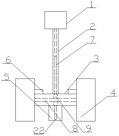
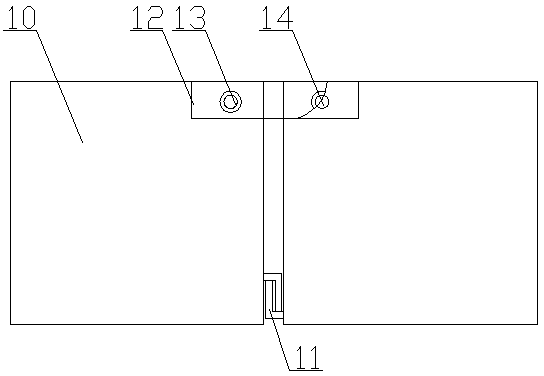
[0021] A three-cutter head dredging machine, including a floating body, a dredging device and a mud discharge device, the floating body includes a plurality of floating body units 10 and a connecting plate 12, and the lower part of the connecting surface of the adjacent floating body units 10 is provided with a facing Up or down the right-angled clasp 11, the upper part of the adjacent outer surface of the two floating body units 10 is provided with a pin hole 14, and the connecting plate 12 is connected to the sides of the two adjacent floating body units, and the connecting plate 12 is provided with There is a connection hole corresponding to the pin hole 14, and a pin 13 is installed in the connection hole; the dredging device includes a row frame 2 and a power unit 1, and the tail end of the row frame 2 is installed on the bow of t...


PUM


Abstract

The invention relates to a silt remover with three cutter heads. The silt remover comprises a floating body, a silt removing device and a mud discharging device. The floating body comprises a plurality of floating body units and connecting plates; the silt removing device comprises a truss and a power device, a reamer rest which is perpendicular to the truss is arranged at the head of the truss, and bucket-wheel type reamers are respectively mounted at two ends of the reamer rest; the mud discharging device comprises two mud sucking openings, a reversing chamber and mud discharging pipes. The silt remover has the advantages that mud can be discharged by double pipelines, two mud sucking pipes are respectively arranged in bucket wheels of the double bucket-wheel type reamers, extend into the reamers and can suck mud which is just generated, the left reamer can remove silt when the truss of the silt remover removes the silt leftwards, the mud can be sucked by the left mud sucking opening, a right inlet is closed by a partition plate in the reversing chamber at the moment, the right mud sucking opening is closed, accordingly, influence of water suction actions of the right mud sucking opening on the efficiency of a mud pump and decrease of the content of the mud in mud water pumped by the mud pump can be effectively prevented, the silt removing efficiency can be improved, and the silt concentration can be increased.

Description

technical field [0001] The invention relates to a desilting machine, in particular to a three-blade desilting machine. Background technique [0002] The dredging machines commonly used in the existing dredging field are generally the dredging head single twist suction type and single bucket wheel type. The disadvantage is that the dredging is serious, and it is easy to cause secondary pollution to the construction water area, resulting in unqualified dredging. Accurate positioning and complete cleaning cannot be achieved under the working conditions of continuous flow, narrow river channel, and low water level. The dredging effect of the double-bucket-wheel dredger is significantly improved, but there is also the problem of serious back-silting. At the same time, when the silt at the bottom of the river is hard, the double-bucket-wheel reamer will dredge downward, but the winch It is easy to shelve on the river bed, causing the reamer to not be able to go deep...

Claims


Application Information

Patent Timeline
Patent Type & Authority Applications(China)
IPC IPC(8): E02F5/28
Inventor 卜建余
Owner 卜建余
Why Eureka
Try Eureka