Pressure swing adsorption gas purifier
A pressure swing adsorption and purifier technology, applied in chemical instruments and methods, using solid contact hydrogen separation, dispersed particle separation, etc., can solve the problems of inability to provide high-purity hydrogen, cumbersome construction process, long intake time, etc., to achieve Easy assembly, structural integration, and low cost effects
- Summary
- Abstract
- Description
- Claims
- Application Information
AI Technical Summary
Problems solved by technology
Method used
Image
Examples
Embodiment 1
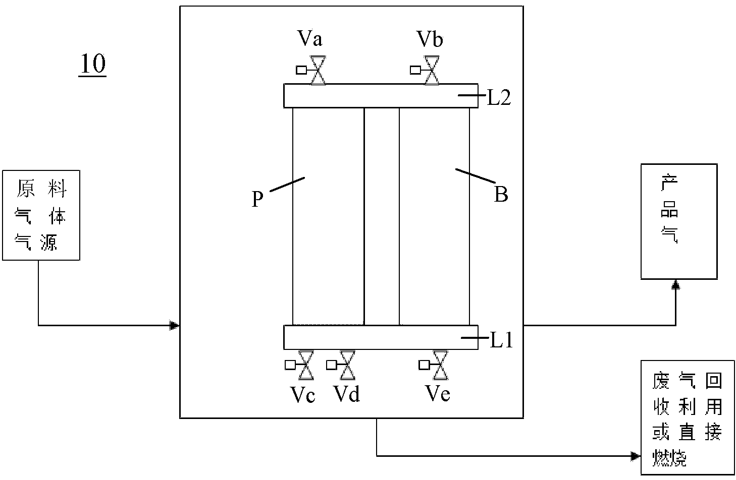
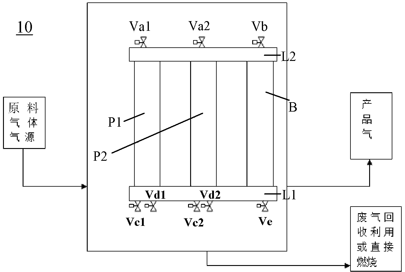
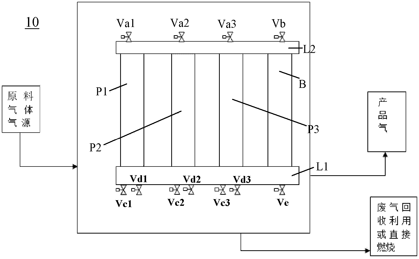
[0117] Adopt the above-mentioned purification tank-product gas buffer tank type PSA purifier of the present invention, wherein, the above-mentioned built-in isolation device of the present invention is not installed in the purification tank, but adopt three layers of 10 purposes respectively at the upper and lower ends of the adsorption bed The high-density wire mesh is used to hold the adsorbent located therein, and the bottom of the purification tank is not filled with the above-mentioned porous plastic pellets of the present invention. For mainly containing H 2 , and contains a small amount of H 2 O, CO, CO 2 The mixed raw material gas is purified, the specific operation process is as follows: firstly open the raw material gas inlet valve of the purification tank, so that the raw material gas to be purified enters the purification tank for purification, and the purified product gas is discharged from the product gas outlet valve of the purification tank and passes through ...
Embodiment 2
[0121] Adopt the above-mentioned purification tank-product gas buffer tank type PSA purifier of the present invention, wherein, the above-mentioned built-in isolation device of the present invention is respectively installed at the upper and lower ends of the adsorption bed in the purification tank, for holding the adsorbent located therein , but the bottom of the purification tank is not filled with the above-mentioned porous plastic pellets of the present invention. The mode of operation as described in Example 1, for mainly containing H 2 , and contains a small amount of H 2 O, CO, CO 2 The mixed raw material gas is purified, the intake flow rate is 110SLPM, and the cumulative operation time is about 1000 hours, and it still maintains a high hydrogen purity, which can meet the needs of fuel cells (ie ≥99.99%).
[0122] Table 3 Purification data of the purifier with built-in isolation device but not filled with porous plastic beads
[0123]
Embodiment 3
[0125] Adopt the above-mentioned purification tank-product gas buffer tank type PSA purifier of the present invention, wherein, the above-mentioned built-in isolation device of the present invention is respectively installed at the upper and lower ends of the adsorption bed in the purification tank, for holding the adsorbent located therein , and the bottom of the purification tank is filled with the above-mentioned porous plastic pellets of the present invention. The mode of operation as described in Example 1, for mainly containing H 2 , and contains a small amount of H 2 O, CO, CO 2 The mixed raw gas is purified. The intake flow rate is 110SLPM, and the cumulative operation is more than 2000 hours, and the hydrogen purity has no obvious change.
[0126] Table 4 Purification data of the purifier with built-in isolation device and filled with porous plastic beads
[0127]
[0128] Effect of Adsorbent Selection on Product Gas Purity and Yield
[0129] The pressure sw...
PUM
 Abstract
Description
Claims
Application Information
 - R&D
- Intellectual Property
- Life Sciences
- Materials
- Tech Scout
- Unparalleled Data Quality
- Higher Quality Content
- 60% Fewer Hallucinations
Browse by: Latest US Patents, China's latest patents, Technical Efficacy Thesaurus, Application Domain, Technology Topic, Popular Technical Reports.
© 2025 PatSnap. All rights reserved.Legal|Privacy policy|Modern Slavery Act Transparency Statement|Sitemap|About US| Contact US: help@patsnap.com


