Steering system and method for automotive vehicle

a steering system and automotive technology, applied in the direction of steering initiation, instruments, vessel construction, etc., can solve the problems of motor and its drive circuit overheating, excessive current command value outputted to the steering actuator, etc., and achieve the effect of preventing an overheating of the steering actuator

Inactive Publication Date: 2006-03-02
NISSAN MOTOR CO LTD
View PDF2 Cites 39 Cited by
  • Summary
  • Abstract
  • Description
  • Claims
  • Application Information

AI Technical Summary

Benefits of technology

[0006] It is, therefore, an object of the present invention to provide steering system and me...

Problems solved by technology

However, in the previously proposed steer by electric wire system, when it becomes impossible for steerable road wheels to be steered in a steering angle increase direction, for example, in a case where the steerable road wheels are mounted on a curb during a stat...

Method used


Image

  • Steering system and method for automotive vehicle
  • Steering system and method for automotive vehicle
  • Steering system and method for automotive vehicle

Examples


first embodiment

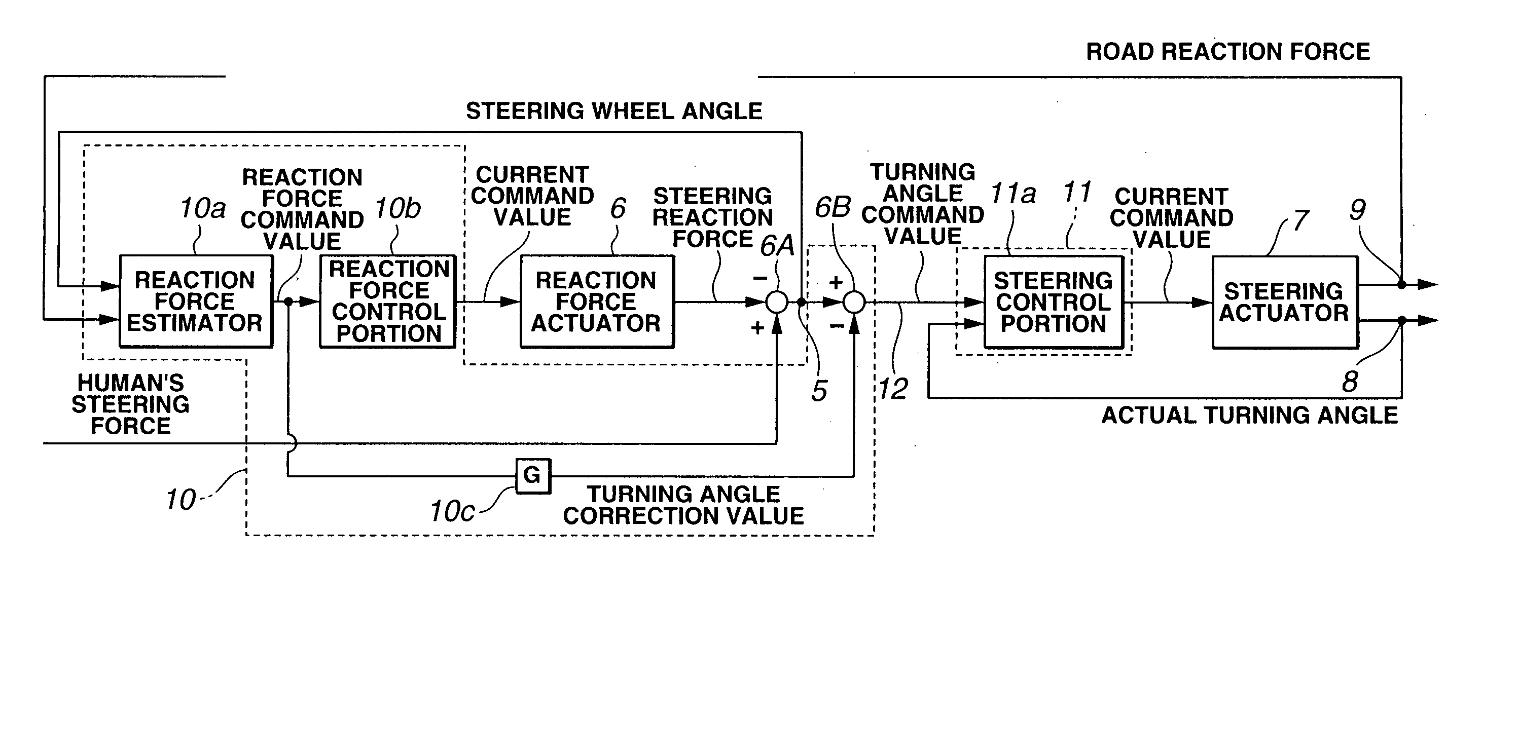
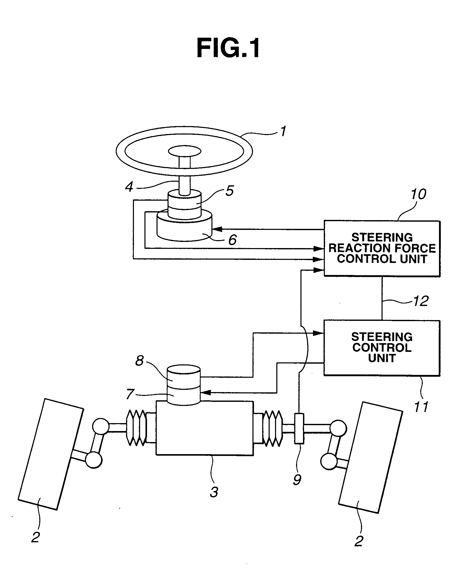
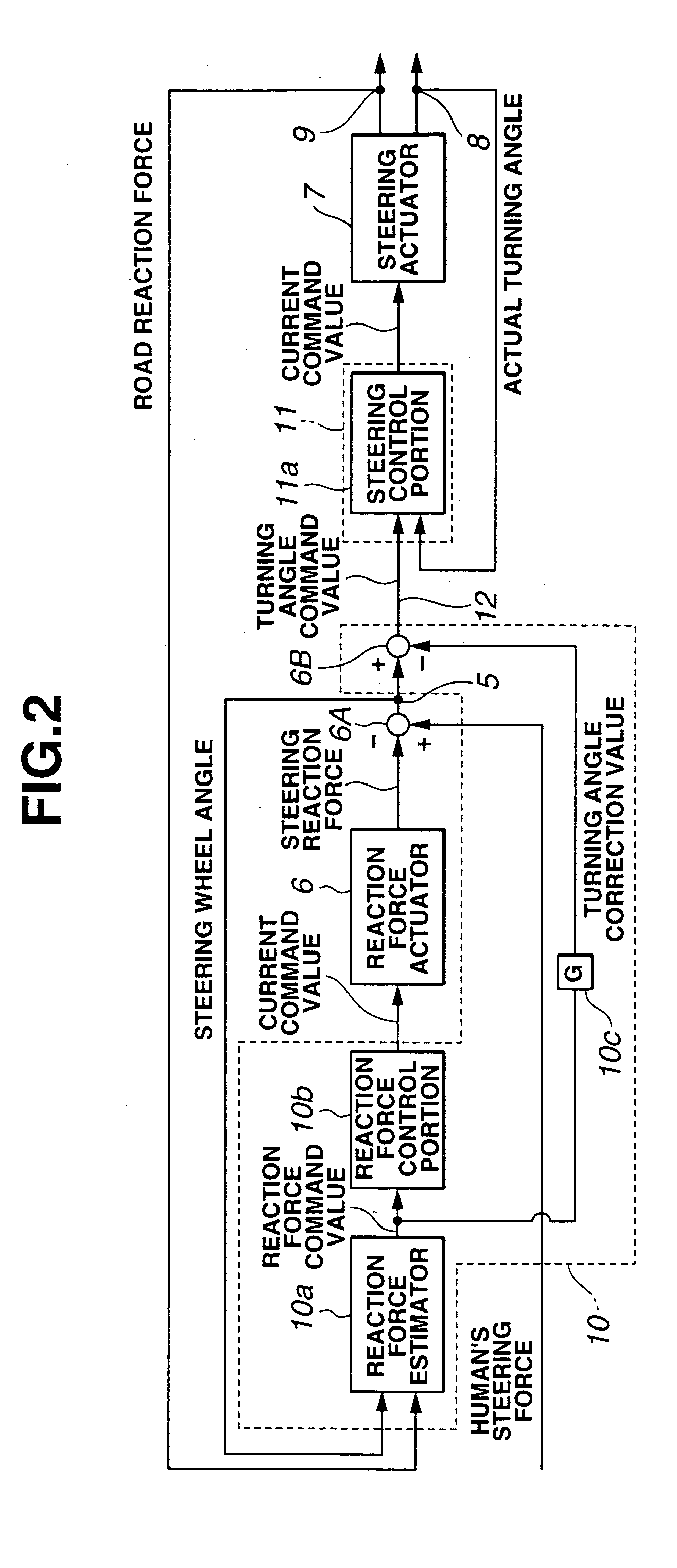
[0018]FIG. 1 shows a whole system configuration of a, so-called, steer by electrical wire system to which a vehicular steering system in a first preferred embodiment according to the present invention is applicable. The steering system in the first embodiment includes: a steering wheel (operation inputting section (means)) 1; steered (steerable) vehicle wheels 2, 2; a steering mechanism 3; a column shaft 4; a steering wheel angle sensor 5; a reaction force actuator 6; a steering (or turning) actuator 7; a steer angle (or turning angle) sensor 8; a force sensor 9; a steering reaction force control unit 10; and a steering (or turning) control unit 11.

[0019] Steering wheel angle sensor 5 which detects a steering angle of steering wheel (operation inputting section (means) 1 which is the steering angle of the driver inputted through steering wheel 1 (also called, a steering wheel angle) and reaction force actuator 6 which gives a steering reaction force to steering wheel 1 are disposed ...

second embodiment

[0052] Next, a second preferred embodiment of the vehicular steering system will be described below. In the second embodiment, the value of correction gain G is varied in accordance with a running situation of the vehicle.

[0053]FIG. 4 shows a control block diagram representing steering reaction force control unit 10′ and steering control unit 11 in the second embodiment. Steering reaction force control unit 10′ in the second embodiment is different from the first embodiment in that, in turning angle correction value setting section 10c′, correction gain G is set on the basis of a vehicle speed V and steering wheel angle θ. The other structure of the steering system is the same as described in the first embodiment. Thus, the same reference numerals as those described in the first embodiment designate like components and the detailed description thereof will herein be omitted.

[0054] Steering angle correction value setting section 10c′ compares first gain Gv obtained from a map shown ...


PUM


Abstract

In steering system and method for an automotive vehicle, a reaction force actuator is configured to provide a steering reaction force for the operation inputting section on the basis of a reaction force command value which accords with a state of steerable wheels, a steering actuator is configured to drive the steering mechanism on the basis of a turning angle command value which accords with a steering angle of the operation inputting section, a turning angle correction value setting section sets a turning angle correction value on the basis of the reaction force command value, and a turning angle command value correcting section subtracts the turning angle correction value from the turning angle command value, the turning angle correction value being set in such a manner that, as the reaction force command value becomes larger, the turning angle correction value becomes larger.

Description

BACKGROUND OF THE INVENTION [0001] 1. Field of the Invention [0002] The present invention relates to a technical field of steering system and method for an automotive vehicle in which a, so-called, steer by electric wire system in which steering (operation) inputting means and a steering mechanism are mechanically separated from each other has been adopted. [0003] 2. Description of the Related Art [0004] A Japanese Patent Application First (Tokkai) Publication No. 2001-191937 published on Jul. 17, 2001 exemplifies a previously proposed steer by electric wire system in which a steering actuator is driven according to a current command value which accords with a steering angle of a steering wheel and a steer (or turning) angle control of steerable (or steered) (road) wheels is carried out. SUMMARY OF THE INVENTION [0005] However, in the previously proposed steer by electric wire system, when it becomes impossible for steerable road wheels to be steered in a steering angle increase dir...

Claims


Application Information

Patent Timeline
IPC IPC(8): B62D5/04
CPCB62D5/006B62D6/008B62D5/0469
Inventor KATOU, YUUSUKE
Owner NISSAN MOTOR CO LTD
Why Eureka
Try Eureka