Lane changing control method and device of autonomous vehicle

A technology for automatic driving and vehicles, applied in control devices, vehicle components, transportation and packaging, etc., can solve problems such as step jumps in the preview trajectory, poor ride comfort, sudden increase in lateral acceleration at lateral corners, etc. The effect of smooth changes, alleviating poor ride comfort, and improving ride comfort

Active Publication Date: 2017-09-29
地壳机器人科技有限公司
View PDF8 Cites 40 Cited by
  • Summary
  • Abstract
  • Description
  • Claims
  • Application Information

AI Technical Summary

Problems solved by technology

Changgui’s self-driving car first determines the current preview trajectory when changing lanes, and then translates the current preview trajectory in the direction of the lane change. However, the above method is likely to cause a step jump in the preview trajectory, which will cause automatic driving. Sudden increase in the lateral cornering angle and lateral acceleration of the car, resulting in poor ride comfort

Method used


Image

  • Lane changing control method and device of autonomous vehicle
  • Lane changing control method and device of autonomous vehicle
  • Lane changing control method and device of autonomous vehicle

Examples


Embodiment 1

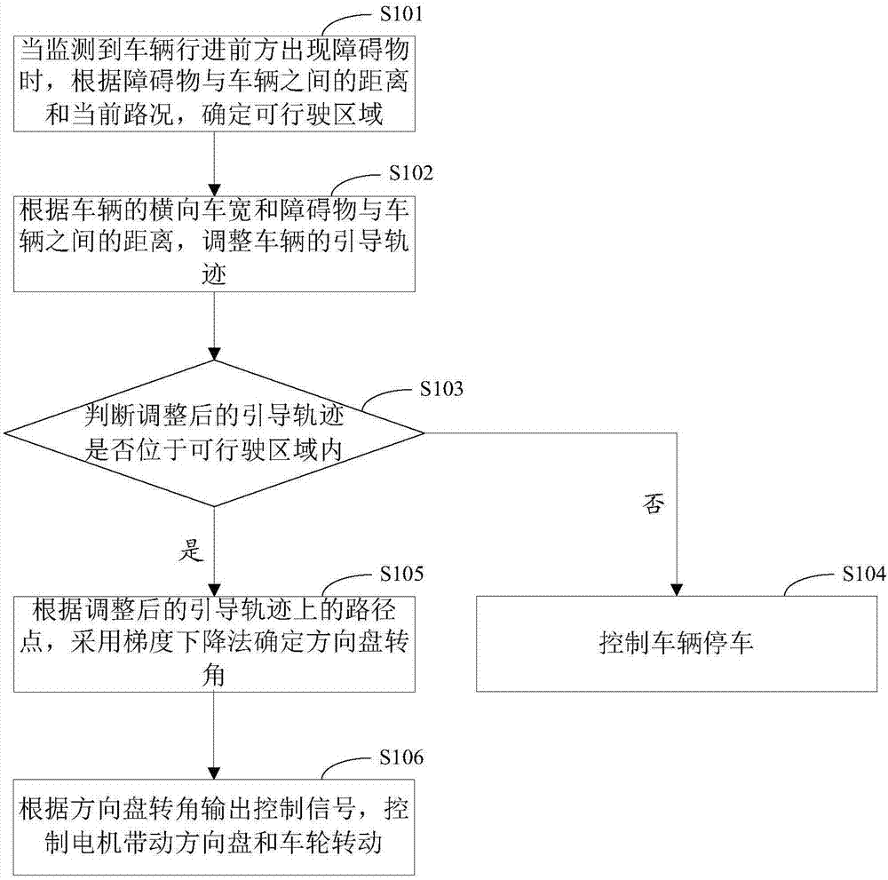
[0062] This embodiment provides a lane change control method for an automatic driving vehicle, the flow chart of the method is as follows figure 1 shown, including the following steps:

[0063] Step S101, when an obstacle is detected in front of the vehicle, the drivable area is determined according to the distance between the obstacle and the vehicle and the current road conditions.

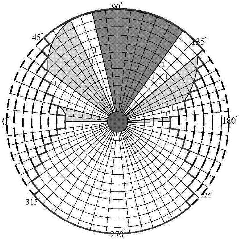
[0064] Among them, the distance between the obstacle and the vehicle and the current road condition can be obtained by sensors such as radar, navigation or camera. According to the data transmitted by the sensor, the grids in the polar coordinate system are divided into obstacle grids and obstacle-free grids. For example, if figure 2 As shown, fill the data of the sensor in the polar coordinate system and fill it according to binarization. That is, the obstacle grid is filled with 1, and the non-obstacle grid is filled with 0. Considering the movement characteristics of the vehicle itself, a...

Embodiment 2

[0091] This embodiment provides another lane change control method for an automatic driving vehicle, the flow chart of the method is as follows Figure 5 shown, including the following steps:

[0092] Step S501, when an obstacle is detected in front of the vehicle, a preliminary drivable area is determined according to the distance between the obstacle and the vehicle and the current road conditions. The specific implementation method can refer to the method of marking and counting in the polar coordinate system described in the first embodiment.

[0093] Step S502, determine whether the current road section where the vehicle is located is a structured road; if yes, execute step S503; if not, consider the current road section as an unstructured road, and execute step S504.

[0094] According to the pre-stored electronic map data, it can be determined that the current road section where the vehicle is located is a structured road or an unstructured road. For structured two-wa...

Embodiment 3

[0132] Corresponding to the above method embodiments, this embodiment provides a lane change control device for an automatic driving vehicle. Such as Figure 10 As shown, the device includes:

[0133] The drivable area calibration module 901 is configured to determine the drivable area according to the distance between the obstacle and the vehicle and the current road conditions when an obstacle is detected in front of the vehicle.

[0134] The guiding trajectory adjustment module 902 is configured to adjust the guiding trajectory of the vehicle according to the lateral vehicle width of the vehicle and the distance between the obstacle and the vehicle.

[0135] The rotation angle calculation module 903 is used to judge whether the adjusted guidance trajectory is within the drivable area; if so, determine the steering wheel rotation angle by using the gradient descent method according to the waypoints on the adjusted guidance trajectory.

[0136] The signal output module 904 ...


PUM


Abstract

The invention provides a lane changing control method and device of an autonomous vehicle and belongs to the technical field of automobile electronic control. According to the lane changing control method and device provided by an embodiment of the invention, in case of lane changing, an available region is determined first according a distance between an obstacle and the vehicle and current road condition; when an adjusted guide trajectory is within the available region, steering is available to be prepared, and the problem of steering wheel shaking due to repeated tries of lane changing is avoided; in addition, turn angle of a steering wheel is determined by means of a gradient descent method, the angle of the steering wheel is changed gently during lane changing, the problem that sudden increase in the transverse turn angle due to the traditional preview-follower algorithm leads to poor riding comfort is solved, and riding comfort of the autonomous vehicle is improved.

Description

technical field [0001] The present invention relates to the technical field of automotive electronic control, in particular to a lane change control method and device for an automatic driving vehicle. Background technique [0002] Autonomous vehicle driving scenarios need to switch between structured roads and unstructured roads. Under normal circumstances on structured roads, it is necessary to choose the direction of changing lanes in accordance with national traffic rules; however, on unstructured roads, autonomous vehicles need to decide the direction of changing lanes by themselves. Therefore, a reasonable and safe lane-changing direction selection in complex environments is crucial to the operation of unmanned vehicles. Changgui’s self-driving car first determines the current preview trajectory when changing lanes, and then translates the current preview trajectory in the direction of the lane change. However, the above method is likely to cause a step jump in the pre...

Claims


Application Information

Patent Timeline
Patent Type & Authority Applications(China)
IPC IPC(8): B60W30/18B60W10/20
CPCB60W10/20B60W30/18163B60W2520/10B60W2540/18B60W2554/00
Inventor 洪灿雄
Owner 地壳机器人科技有限公司
Why Eureka
Try Eureka