Clock multiplying delay-locked loop for data communications

Inactive Publication Date: 2005-10-04
RAMBUS INC
View PDF23 Cites 32 Cited by
  • Summary
  • Abstract
  • Description
  • Claims
  • Application Information

AI Technical Summary

Benefits of technology

[0011]The present invention overcomes the jitter problems of prior art data communication systems based on PLLs and multi-phase DLLs. Unlike a PLL, the multiplying DLL of the present invention does not accumulate phase error from cycle to cycle of the reference clock. The phase error is reset to zero on each rising edge of the reference clock. Thus, for a giv

Problems solved by technology

Prior art data communication systems based on PLL clock multipliers and multi-phase DLLs have large amounts of jitter due to the method used to generate timing signals.
Phase-locked loop based clock multipliers have large amounts of jitter because the phase error at the end of each cycle accumulates until the control loop can respon

Method used


Image

  • Clock multiplying delay-locked loop for data communications
  • Clock multiplying delay-locked loop for data communications
  • Clock multiplying delay-locked loop for data communications

Examples


Embodiment Construction

[0033]A description of preferred embodiments of the invention follows.

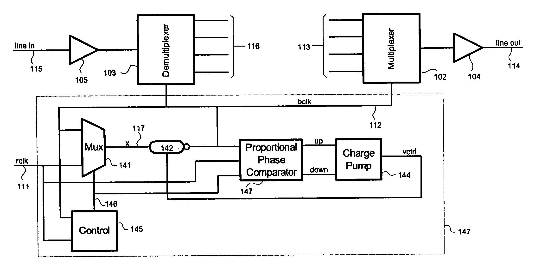
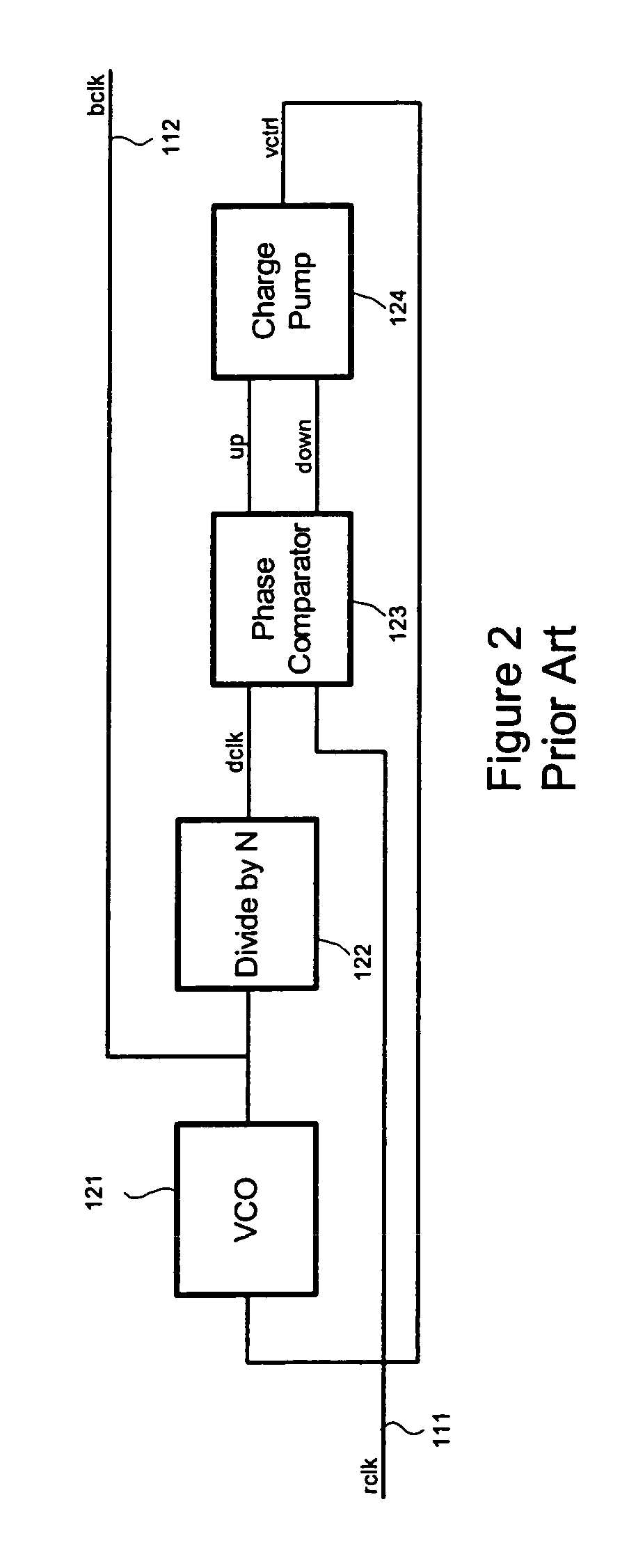
[0034]A clock-multiplying delay-locked loop previously used as a microprocessor clock is illustrated in FIG. 4. Like the PLL of FIG. 2, this loop multiplies the frequency of the reference clock but with loop dynamics that correspond to the DLL of FIG. 3. As shown in FIG. 4, reference clock 111 is input to multiplexer 141, the output of which drives delay line 142 to generate the bit clock (bclk) 112. The bit clock 112 is recirculated back to multiplexer 141 and passed to the delay line 142. The delay through delay line 142 determines the duration of a bclk pulse, and with bclk fed back to the input of the delay line, a ring oscillator is formed to generate multiple bclk pulses for each rclk pulse.

[0035]In operation, control block 145 sets multiplexer control line 146 to select the reference clock as input to the delay line. Then, after a rising edge on the reference clock, control block 145 switches line 146 to re...


PUM


Abstract

In a communications system, data is multiplexed onto a transmission medium at a transmitter and demultiplexed from the transmission medium at a receiver. The clock applied to the transmitter and receiver is a multiplying delay-locked loop in which a delay line provides a multiplied clock which is applied back to its input. A delay adjustment circuit including a proportional phase comparator of low offset adjusts delay in the delay line.

Description

RELATED APPLICATION(S)[0001]This application claims the benefit of U.S. Provisional Application No. 60 / 161,977, filed Oct. 28, 1999, the entire teachings of which are incorporated herein by reference.BACKGROUND OF THE INVENTION[0002]High-speed data communication systems commonly use multiplexing transmitters and demultiplexing receivers. In such a system, as illustrated in FIG. 1, transmit data arrives on a set of parallel lines 113 and is multiplexed onto the transmission line 114. The multiplexer converts the parallel signal at the reference clock rate on lines 113 into a serial signal at the bit clock rate on line 114. At the other end of the link, the serial signal arrives on input line 115 and is demultiplexed onto parallel outputs 116. In such a system, the bit clock that sequences multiplexer 102 and demultiplexer 103 has a frequency that is a multiple of the reference clock 111 used to clock parallel input 113 and parallel output 116. In the example of FIG. 1 where the multi...

Claims


Application Information

Patent Timeline
IPC IPC(8): H04J3/06H03K5/00H03K5/13H03L7/083H03L7/089H03L7/091H03L7/099H03L7/20H04L7/033
CPCH03L7/083H03L7/091H03L7/0995H03L7/20H04L7/0337H03K5/133H03K2005/00026H03K2005/00228H03L7/0891
Inventor DALLY, WILLIAM J.POULTON, JOHN W.
Owner RAMBUS INC
Why Eureka
Try Eureka