Apparatus and method for obtaining object-color component data

a technology of object-color component data and apparatus, which is applied in the field of obtaining image data by digital cameras, can solve the problems that the atmosphere produced by the illumination environment in an image cannot be used by another image, and the image is produced an unnatural imag

Inactive Publication Date: 2006-02-21
MINOLTA CO LTD
View PDF9 Cites 90 Cited by
  • Summary
  • Abstract
  • Description
  • Claims
  • Application Information

AI Technical Summary

Problems solved by technology

Since the data of an image is, however, conventionally treated as integral data, the atmosphere produced by the illumination environment in an image cannot be used by another image.
Further, in the case of

Method used


Image

  • Apparatus and method for obtaining object-color component data
  • Apparatus and method for obtaining object-color component data
  • Apparatus and method for obtaining object-color component data

Examples


first embodiment

1. First Embodiment

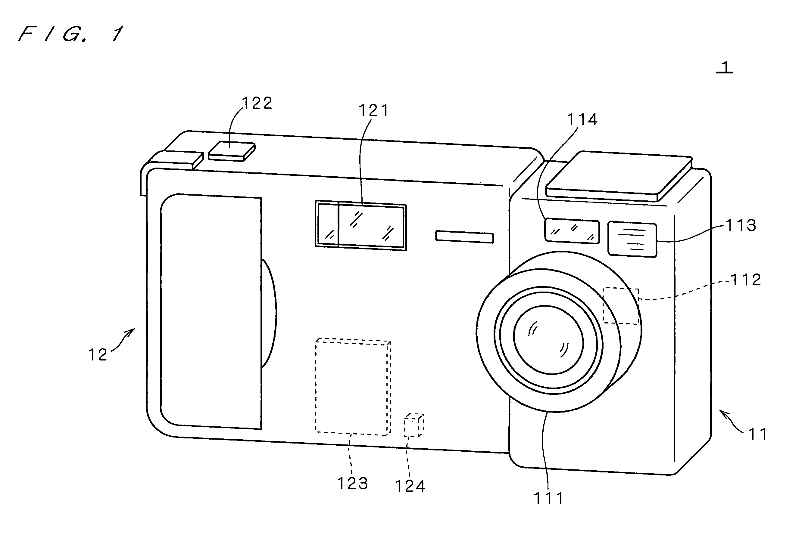
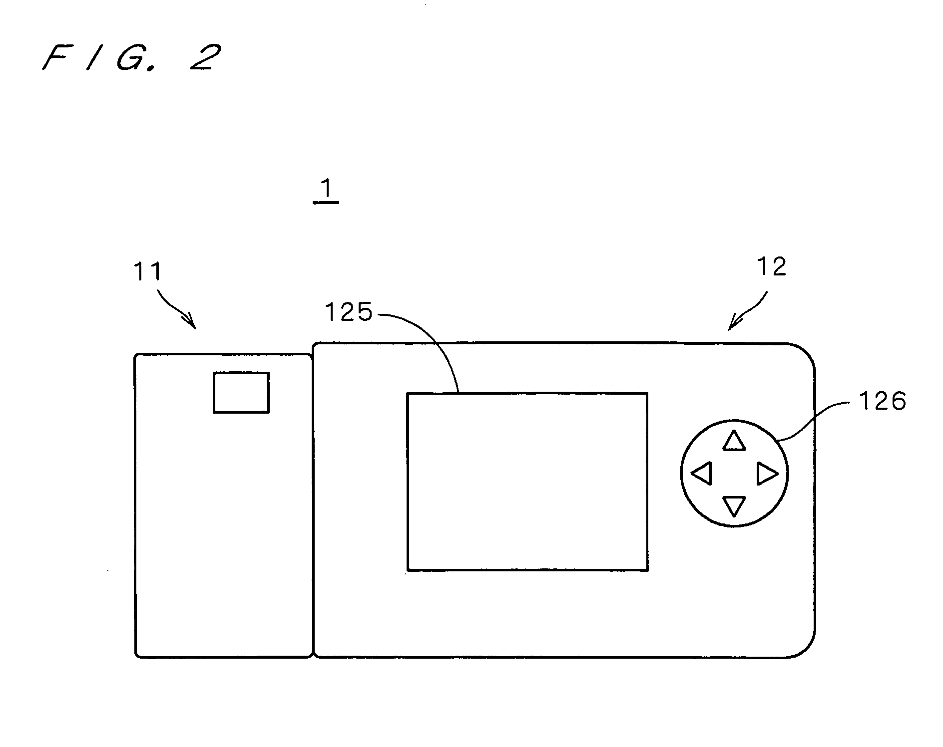
[0043]FIG. 1 is a perspective view showing a whole digital camera 1 as a digital image capturing apparatus according to a first embodiment. The digital camera 1 comprises a lens unit 11 for capturing an image and a main body part 12 for processing an image obtained as digital data by the lens unit 11.

[0044]The lens unit 11 has a lens system 111 having a plurality of lenses and a CCD 112 for capturing an image of a subject via the lens system 111. An image signal outputted from the CCD 112 is sent to the main body part 12. In the lens unit 11, a finder 113 used by the operator to capture the subject, a range sensor 114, and the like are also arranged.

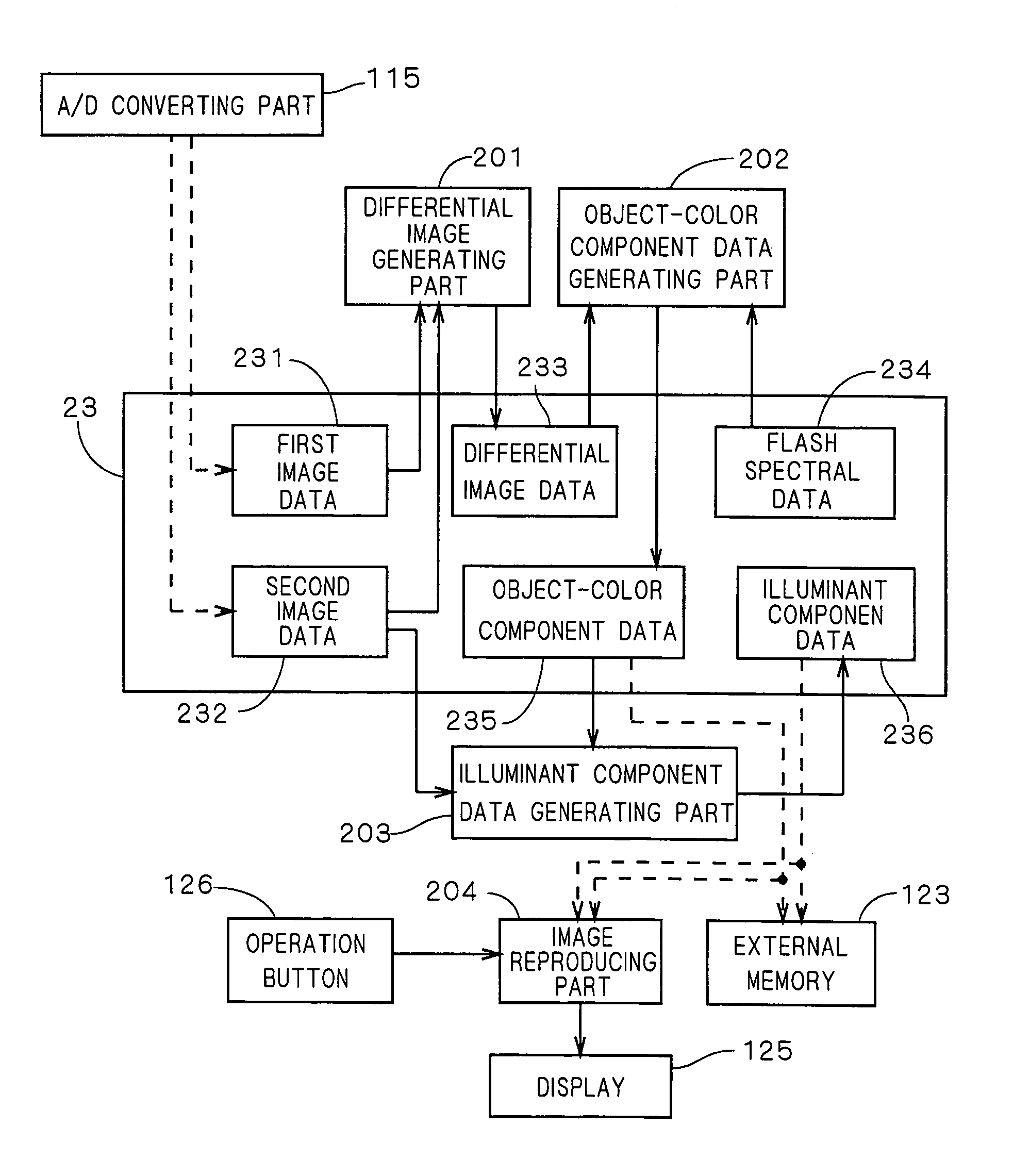
[0045]In the main body part 12, a flash 121 and a shutter button 122 are provided. When the operator captures the subject via the finder 113 and operates the shutter button 122, an image is obtained electrically by the CCD 112. At this time, the flash 121 is used in accordance with necessity. The CCD 112 is 3-band imag...

second embodiment

2. Second Embodiment

[0094]FIG. 15 is a diagram showing the construction of a digital camera 1a according to a second embodiment. As shown in FIG. 15, the digital camera 1a has a filter 116 in front of the CCD 112 of the digital camera 1 in the first embodiment and the filter 116 is movably disposed by the operation of a motor 117. The other construction is similar to that of the first embodiment and the same components as those of FIG. 1 are designated by the same reference numerals.

[0095]In the digital camera 1a, the filter 116 swings around the rotary shaft of the motor 117 as a center between a position on the optical axis of the lens system 111 (that is, on an optical path at the time of image capturing) and a position deviated from the optical path for image capturing. In the second embodiment, object-color component data corresponding to image data from which the influence of illuminance is removed and illuminant component data indicative of the influence of the illumination e...

third embodiment

3. Third Embodiment

[0117]FIG. 21 shows the construction of a digital camera 1b according to the third embodiment. In the digital camera 1a according to the second embodiment, the single filter 116 can be disposed on the optical path for image capturing. The digital camera 1b according to the third embodiment is different from the digital camera 1a according to the second embodiment with respect to the point such that first and second filters 116a and 116b can be disposed on the optical path for image capturing by the operation of the motor 117. The internal construction of FIG. 21 is similar to that of FIG. 16 except for the point that the first and second filters 116a and 116b can be disposed on the optical path for image capturing. FIG. 16 will be referred to with respect to the construction other than the filters.

[0118]FIG. 22 is a block diagram showing the component data generating part 205 realized by the CPU 21, the ROM 22, the RAM 23 and the like in the special image capturin...


PUM


Abstract

First image data is obtained by performing an image capturing operation with a flash and, subsequently, second image data is obtained by performing an image capturing operation without a flash. By using data of a differential image between the first and second image data and a relative spectral distribution of flash light, the spectrum reflectivity in a position on a subject corresponding to each pixel is obtained and object-color component data is acquired as data from which an influence of an illumination environment has been removed. On the other hand, illuminant component data indicative of spectral distributions of a plurality of illumination light are prepared. By combining arbitrary illuminant component data to the obtained object-color component data, an image with a different illumination environment can be reproduced.

Description

[0001]This application is based on application No. 11-247010 filed in Japan, the contents of which are hereby incorporated by reference.BACKGROUND OF THE INVENTION[0002]1. Field of the Invention[0003]The present invention relates to a technique for obtaining image data of a subject and, more particularly, to a technique of obtaining image data by a digital camera or the like.[0004]2. Description of the Background Art[0005]Hitherto, image processes are performed to correct the hue or atmosphere of an image obtained as digital data by an image input device such as a digital camera. A representative one of such processes is a color correction based on white balance. In the correction based on white balance, an image is corrected based on the overall balance of the color of the image so that a white body will appear to be white. This allows the influence of the color of illuminant light on the subject to be removed from the image to some extent, and the image is corrected to one that ag...

Claims


Application Information

Patent Timeline
IPC IPC(8): H04N9/73H04N5/222H04N9/04G03B7/08G03B15/05G03B17/18G06T1/00G06T5/50H04N1/04H04N1/387H04N1/48H04N5/235H04N9/64
CPCG06T5/50H04N9/735H04N5/2354H04N1/387H04N23/74H04N23/88
Inventor UCHINO, FUMIKOUSUI, SHIRONAKAUCHI, SHIGEKITAKEBE, KEISUKE
Owner MINOLTA CO LTD
Why Eureka
Try Eureka