Selective address table aging in a network switch based on application state determined from a received data packet

a network switch and data packet technology, applied in data switching networks, bus networks, digital transmission, etc., can solve problems such as wasting network switch resources, affecting data packet transmission speed, so as to minimize relearning

Inactive Publication Date: 2006-02-21
ADVANCED MICRO DEVICES INC
View PDF13 Cites 22 Cited by
  • Summary
  • Abstract
  • Description
  • Claims
  • Application Information

AI Technical Summary

Benefits of technology

[0010]There is a need for an arrangement that enables a network switch to selectively delete address...

Problems solved by technology

One problem with existing layer 2 type network switches involves use of aging functions having a fixed aging interval, set by a user, to delete aged address entries from network switch address table.
Use of the above-described aging function, however, may cause premature deletion of an address entry from the network switch, requiring the network switch to relearn the network addresses.
For example, the layer 2 switch, unaware that a ...

Method used


Image

  • Selective address table aging in a network switch based on application state determined from a received data packet
  • Selective address table aging in a network switch based on application state determined from a received data packet
  • Selective address table aging in a network switch based on application state determined from a received data packet

Examples


Embodiment Construction

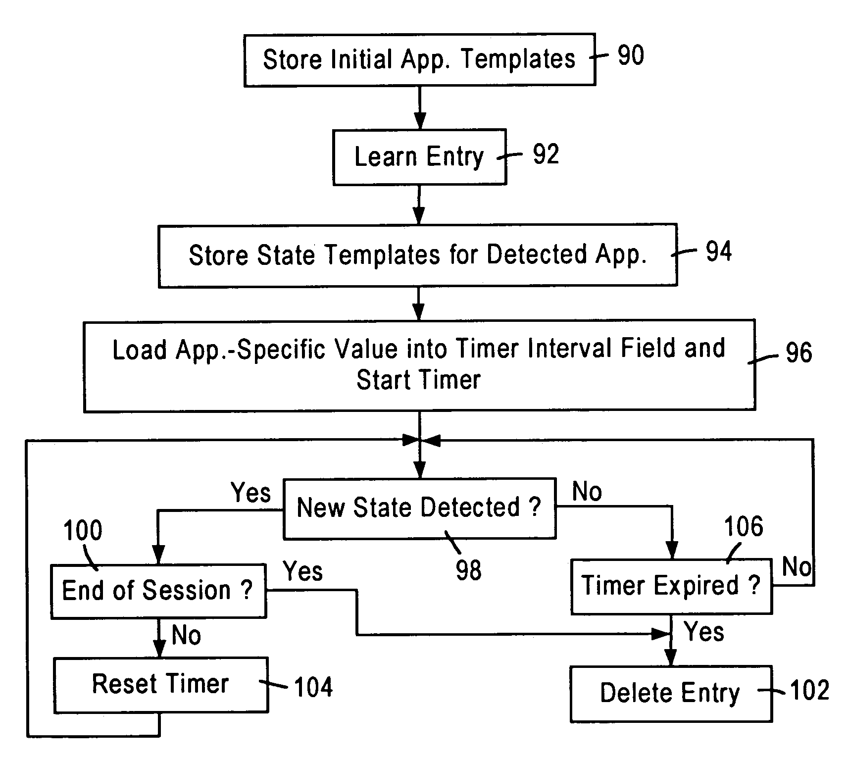
[0022]The disclosed embodiment is directed to an arrangement in an integrated network switch for generating application-based aging intervals for network switch address table entries, and selectively deleting an address entry based on an application state determined for a prescribed network application from a received layer 2 data packet. The detection of a prescribed network application from a received layer 2 data packet, as well as the application state for the prescribed network application, is performed by a packet classifier module within the network switch port having received the layer 2 data packet. A description will first be provided of the network switch architecture and the packet classifier, followed by a description of the application-based aging of the network switch address entries.

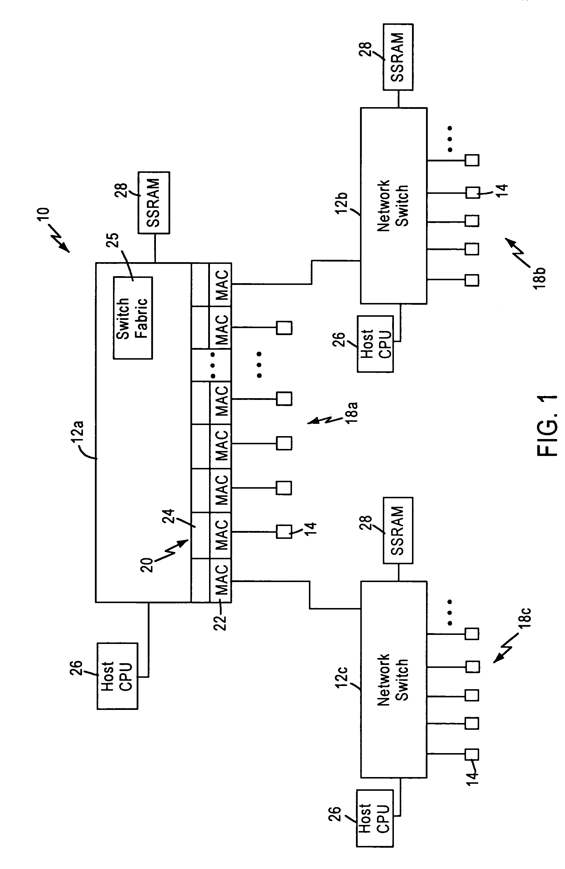
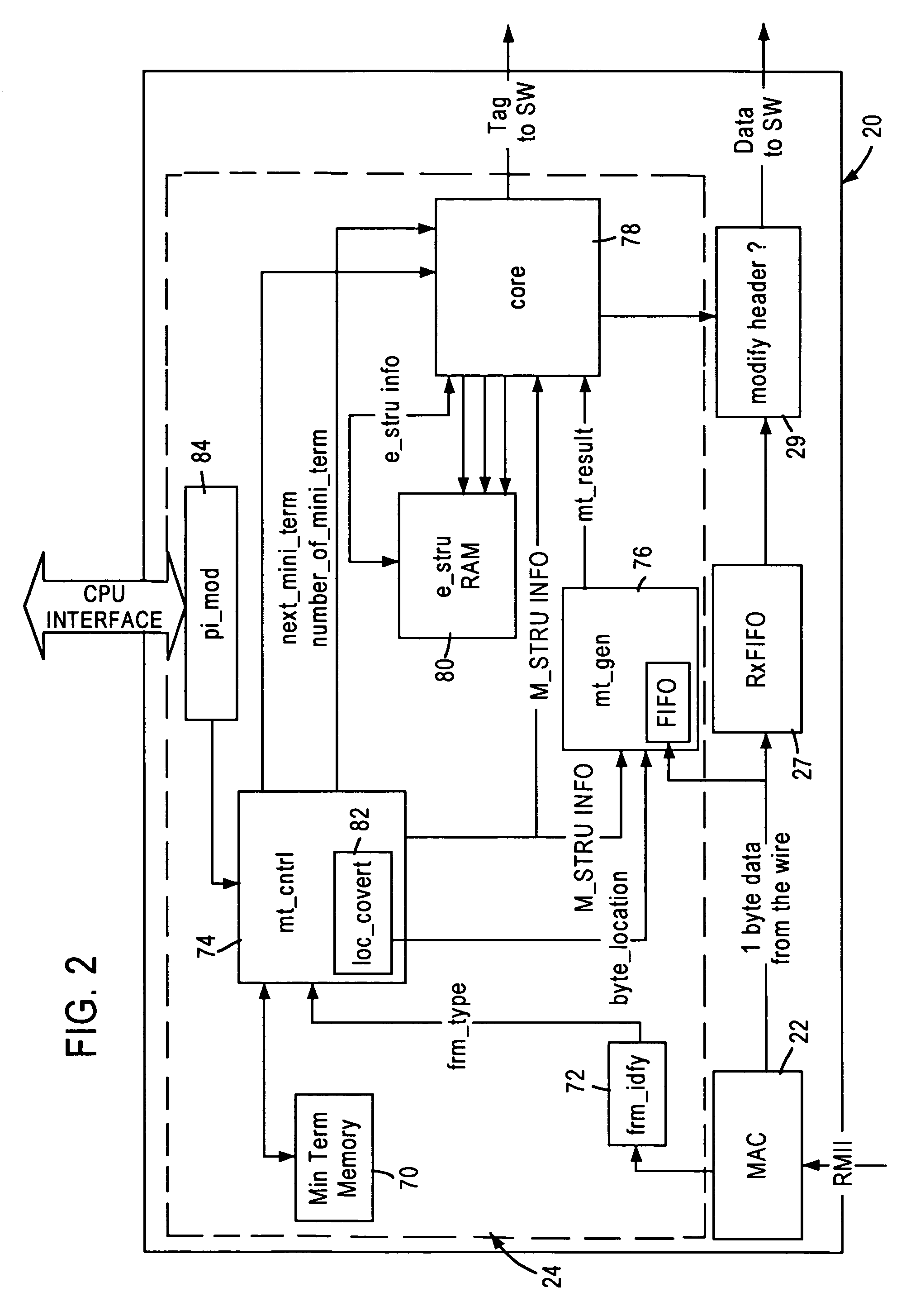
[0023]FIG. 1 is a block diagram illustrating a packet switched network 10, such as an Ethernet (IEEE 802.3) network. The packet switched network includes integrated (i.e., single chip) mu...


PUM


Abstract

A network switch, configured for performing layer 2 and layer 3 switching in an Ethernet (IEEE 802.3) network without blocking of incoming data packets, includes a network switch port having a packet classifier module configured for evaluating an incoming data packet on an instantaneous basis. The packet classifier module performs simultaneous comparisons between the incoming data stream of the data packet and multiple templates configured for identifying respective data protocols. Each template is composed of a plurality of min terms, wherein each min term specifies a prescribed comparison operation within a selected data byte of the incoming data packet. Hence, the packet classifier module is able to monitor data flows between two network nodes interacting according to a prescribed network application. The packet classifier module determines the application state for a prescribed network application from a received layer 2 data packet, enabling switching logic within the network switch to utilize application-specific aging intervals for respective network applications such as HTTP, SNMP, ftp, Telnet, etc. in order to delete aged address entries from a network switch address table based on the supported network application. Determination of the application state from the received layer 2 data packet also enables the network switch to detect the end of a data flow for deletion of the corresponding address entry from the network switch address table.

Description

BACKGROUND OF THE INVENTION[0001]1. Field of the Invention[0002]The present invention relates to switching of data packets in a non-blocking network switch configured for switching data packets between subnetworks.[0003]2. Background Art[0004]Local area networks use a network cable or other media to link stations on the network. Each local area network architecture uses a media access control (MAC) enabling network interface devices at each network node to access the network medium.[0005]The Ethernet protocol IEEE 802.3 has evolved to specify a half-duplex media access mechanism and a full-duplex media access mechanism for transmission of data packets. The full-duplex media access mechanism provides a two-way, point-to-point communication link between two network elements, for example between a network node and a switched hub.[0006]Switched local area networks are encountering increasing demands for higher speed connectivity, more flexible switching performance, and the ability to a...

Claims


Application Information

Patent Timeline
IPC IPC(8): H04L12/56H04L12/40H04L12/46H04L29/06
CPCH04L12/4625H04L69/28H04L12/28
Inventor KANURI, MRUDULAKRISHNA, GOPAL
Owner ADVANCED MICRO DEVICES INC
Why Eureka
Try Eureka