Vehicle having twin transmissions for driving respective wheels

a technology of transmission and respective drive wheels, applied in the field of vehicles, can solve the problems of complicated and troublesome, vehicle to turn to the wrong side, and does not disclose a pair of transmissions for driving respective right and left drive wheels

Inactive Publication Date: 2006-02-28
SICOR SOC ITAL CORTICOSTEROIDI SPA +1
View PDF13 Cites 38 Cited by
  • Summary
  • Abstract
  • Description
  • Claims
  • Application Information

AI Technical Summary

Benefits of technology

[0017]These, further and other objects, features and advantages will appear more ful

Problems solved by technology

However, the vehicle having the twin transmissions still has such a problem as follows: When it is assumed that the left drive wheel is decelerated and the right wheel accelerated by turning the steering wheel leftward during the forward traveling of the vehicle, the steering wheel must be turned rightward for left turning during the rearward traveling of the vehicle because the acceleration force for a forwardly rotating wheel serves as a deceleration force for a rearwardly rotating wheel.
Such an operation of the st

Method used


Image

  • Vehicle having twin transmissions for driving respective wheels
  • Vehicle having twin transmissions for driving respective wheels
  • Vehicle having twin transmissions for driving respective wheels

Examples


Embodiment Construction

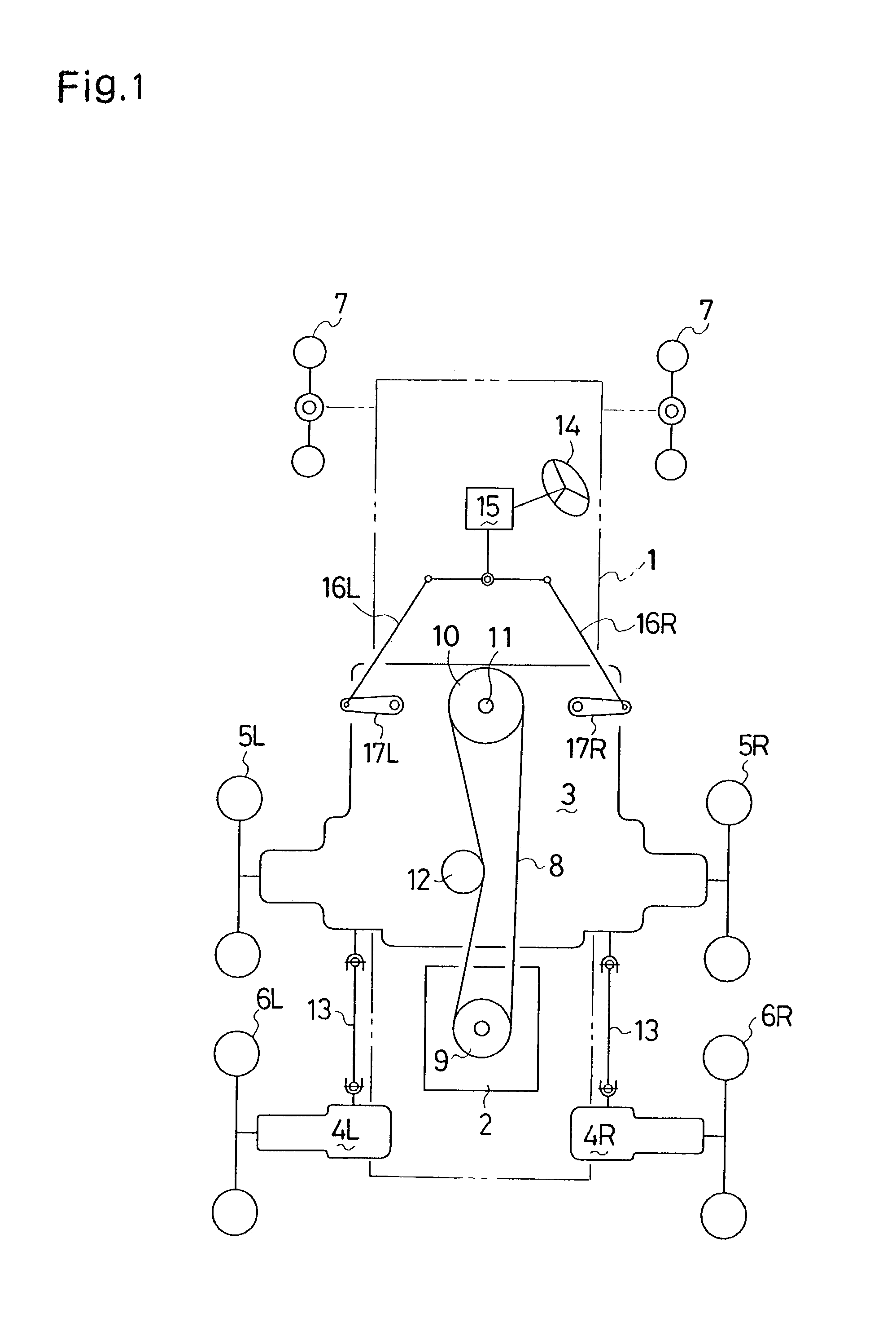
[0031]Referring to FIG. 1, a six-wheel vehicle has a vehicle frame 1, on which a vertical crankshaft engine 2, a transmission housing 3 and left and right axle casings 4L and 4R are mounted. Left and right drive wheels 5L and 5R are disposed on left and right sides of transmission housing 3, respectively. Left and right drive wheels 6L and 6R are disposed behind respective drive wheels 5L and 5R. Left and right casters 7 are supported (alternatively, only one caster 7 or more than two casters 7 may be supported) by a front portion of vehicle frame 1 so as to serve as laterally turnable driven wheels, which are free from driving power of engine 2 and turn to a lateral side coinciding with a turning side of a steering wheel 14 serving as a steering operation device. Thus, in this vehicle, casters 7 serve as front wheels, drive wheels 5L and 5R as middle wheels, and drive wheels 6L and 6R as rear wheels. However, positions of these wheels may be changed in the longitudinal direction of...


PUM


Abstract

A vehicle comprises a vehicle frame, a prime mover mounted on the vehicle frame, a laterally turnable wheel disposed at one side of the vehicle frame, a pair of drive wheels disposed at the other side of the vehicle frame, a steering operation device, a traveling operation device for setting the traveling speed and direction of the vehicle, and a pair of transmissions for controlling the rotary speed and direction of the respective drive wheels. The transmissions are operationally connected with the steering operation device so as to create a difference of rotary speed between the drive wheels according to operation of the steering operation device. The transmissions are operationally connected with the traveling operation device so as to drive the drive wheels in a common rotary direction from their stationary state according to operation of the traveling operation device. A clutch is interposed between the transmissions so as to connect the drive wheels with each other when the steering operation device is set in a straight traveling position. Based on setting of a switching device for switching the traveling direction of the vehicle between forward and rearward, a reverser decides the rotational direction of the drive wheels.

Description

BACKGROUND OF THE INVENTION[0001]1. Field of the Invention[0002]The present invention relates to a vehicle equipped with a pair of transmissions, e.g., a pair of hydrostatic transmissions (HSTs), a pair of belt type continuous variable transmissions (CVTs), or a pair of electric motors, for driving respective left and right drive wheels, wherein the pair of transmissions, which surely drive the vehicle straight when they are set so, are operated for left and right turning of the vehicle so that one of the left and right drive wheels is accelerated and the other is decelerated, and wherein each of the left and right turning directions of the vehicle always coincides with the manipulated leftward or rightward direction of a steering operation device whether the vehicle travels forward or rearward.[0003]2. Related Art[0004]There is a well-known vehicle having twin parallel transmissions, such as HSTs, for driving respective left and right drive wheels. For left and right turning of the...

Claims


Application Information

Patent Timeline
IPC IPC(8): B62D11/04B60K17/10B60K17/356B60K17/36B62D3/02B62D7/09B62D11/00
CPCB60K17/10B60K17/356B60K17/36B62D11/24B62D7/09B62D11/005B62D11/006B62D3/02
Inventor IRIKURA, KOJI
Owner SICOR SOC ITAL CORTICOSTEROIDI SPA
Why Eureka
Try Eureka