Rotating blowout preventer with independent cooling circuits and thrust bearing

a technology of rotating blowout preventer and independent cooling circuit, which is applied in the direction of packaging, closures, and fluid removal. it can solve the problems of affecting the wear rate of seals

Inactive Publication Date: 2006-02-28
WEATHERFORD CANADA PARTNERSHIP
View PDF29 Cites 91 Cited by
  • Summary
  • Abstract
  • Description
  • Claims
  • Application Information

AI Technical Summary

Benefits of technology

[0010]This rotary blowout preventer has a first and a second pressurized fluid circuit. Each of the fluid circuits are defined into and out of a stationary body and between the stationary body, a rotating body, and two seals. The first fluid circuit is physically independent from the second fluid circuit although they share a seal interface. A fluid is introduced into the first fluid circuit at a pressure responsive to the well bore pressure. A fluid is introduced into the second fluid circuit at a pressure...

Problems solved by technology

Such pressures affect ...

Method used


Image

  • Rotating blowout preventer with independent cooling circuits and thrust bearing
  • Rotating blowout preventer with independent cooling circuits and thrust bearing
  • Rotating blowout preventer with independent cooling circuits and thrust bearing

Examples


Embodiment Construction

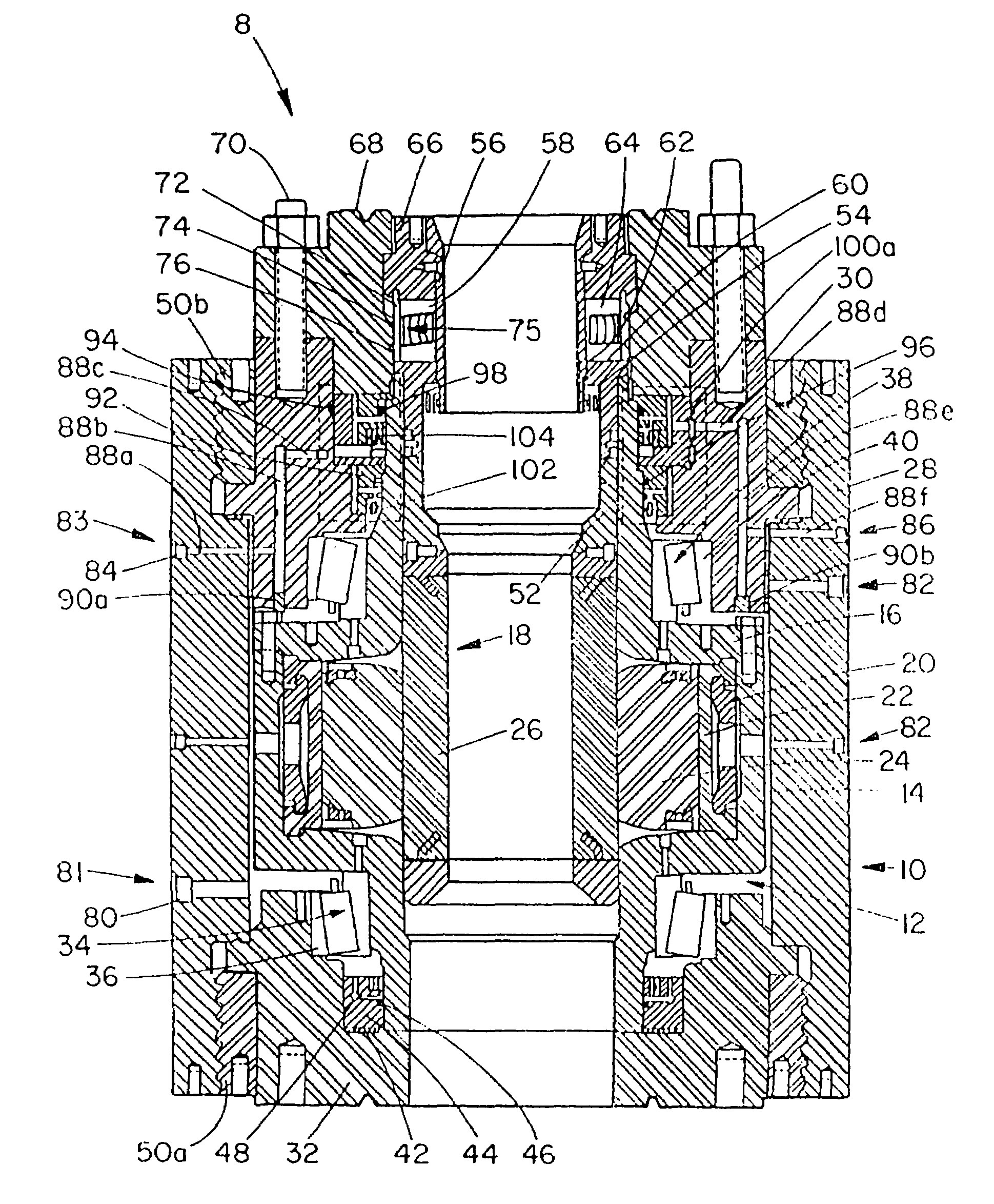
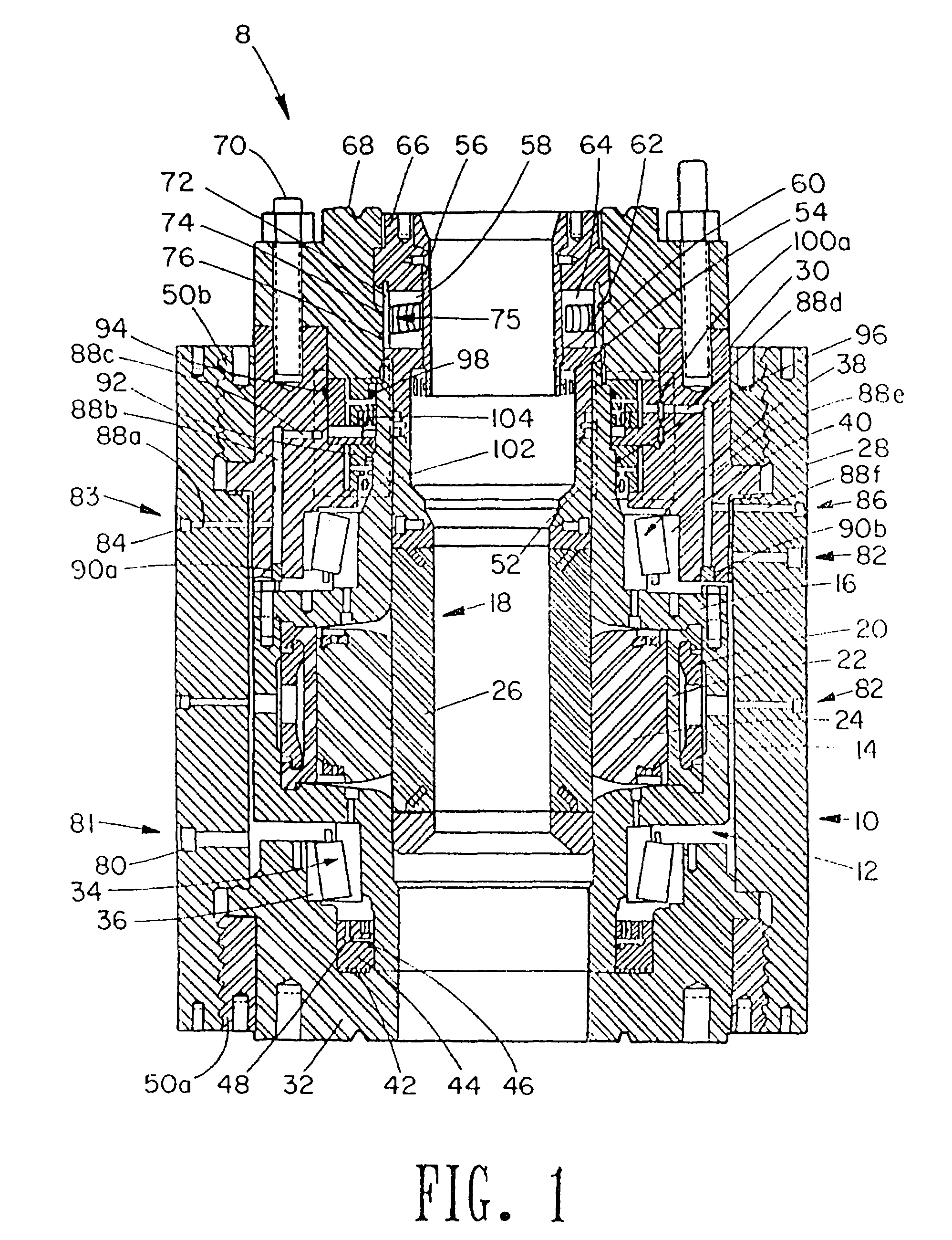
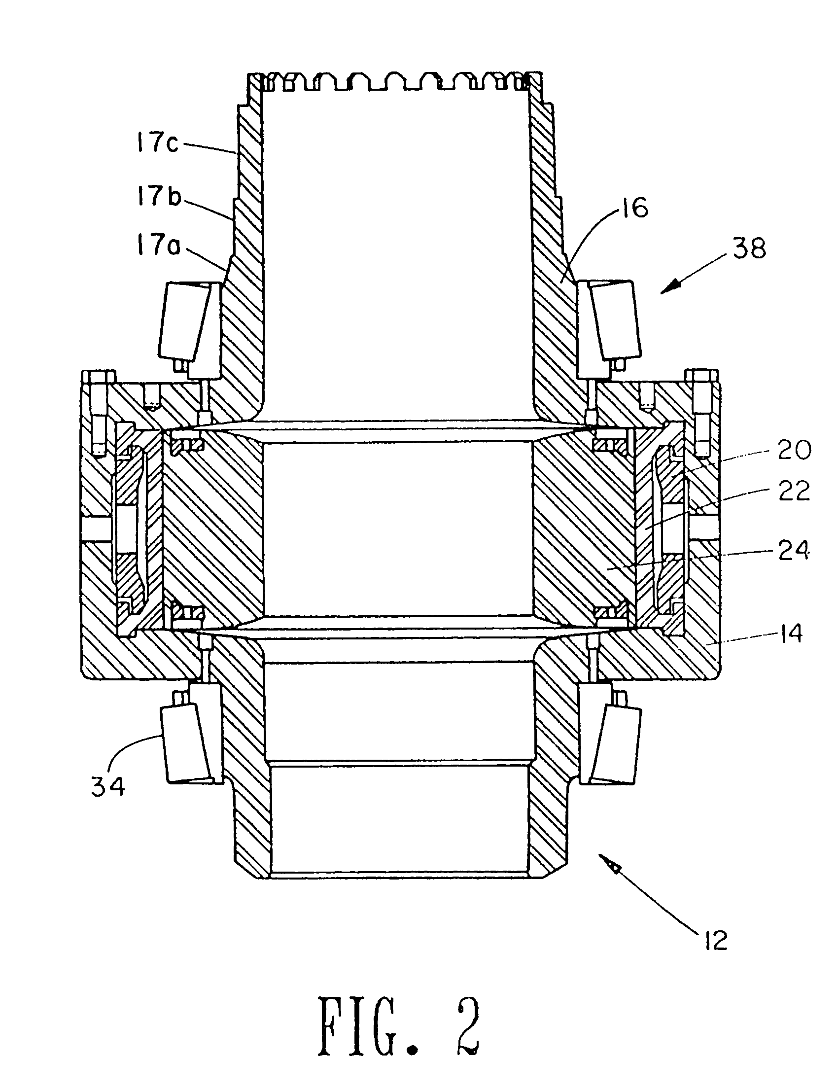
[0016]Referring to FIGS. 1 and 2, the rotating blowout preventer 8 generally includes a stationary body 10 which houses a rotating body 12. The rotating body 12 includes a rotating housing 14, a rotating housing cover plate 16 and a packer assembly 18. The packer assembly 18 has a split keeper ring 20, an outer packer 22, an inner packer 24 and a packer sleeve 26. The stationary body 10 generally includes a body 28 with a top closure 30 and a bottom closure flange 32.

[0017]A lower bearing 34 is mounted between the stationary body 10 and the rotating body 12 in a cup 36. An upper bearing 38 is mounted between the stationary body 10 and the rotating body 12 against a cup 40. A bottom thrust bearing 42 is mounted between the stationary body 10 and the rotating body 12 on the bottom closure flange 32.

[0018]A first or bottom seal carrier 44 is mounted between the stationary body 10 and the rotating body 12 and includes a groove for the mounting of a first seal 46, which may, for example,...


PUM


Abstract

A rotary blowout preventer has a first and a second fluid circuit. Each of the fluid circuits are defined into and out of a stationary body and between the stationary body, a rotating body, and two seals. The first fluid circuit is physically independent from the second fluid circuit although they share a seal interface. A fluid is introduced into the first fluid circuit at a pressure responsive to the well bore pressure. A fluid is introduced into the second fluid circuit at a pressure responsive to and lower than the pressure of the fluid in the first circuit. Adjustable orifices are connected to the outlet of the first and second fluid circuits to control such pressures within the circuits. Such pressures affect the wear rates of the seals. The system can therefore control the wear rate of one seal relative to another seal. A thrust bearing is added to share the load placed upon the upper bearings. The thrust bearing is connected between the top end of a packer sleeve and the stationary body.

Description

CROSS-REFERENCE TO RELATED APPLICATIONS[0001]This application is a divisional of U.S. patent application Ser. No. 10 / 423,105 filed Apr. 25, 2003 (U.S. Pat. No. 6,749,172) which is a divisional of U.S. patent application Ser. No. 09 / 735,385, filed Dec. 12, 2000 (U.S. Pat. No. 6,554,016) and claims the benefit of same.STATEMENTS REGARDING FEDERALLY SPONSORED RESEARCH OR DEVELOPMENT[0002]Not applicable.REFERENCE TO A MICROFICHE APPENDIX[0003]Not applicable.BACKGROUND OF THE INVENTIONDescription of the Related Art[0004]U.S. Pat. No. 5,178,215 serves as a starting point for the departure made by the present invention. The disclosure of U.S. Pat. No. 5,178,215 is incorporated herein by reference and includes a general discussion of an existing rotary blowout preventer which is fluid actuated to grip a drill pipe or kelly, and the controlled circulation of a fluid to lubricate and cool bearings and seals, and to filter particulate matter.[0005]These existing rotary blowout preventers have ...

Claims


Application Information

Patent Timeline
IPC IPC(8): E21B33/06E21B33/08E21B34/16
CPCE21B33/085E21B34/16Y10S277/927Y10T137/0379
Inventor KINDER, JOSEPH
Owner WEATHERFORD CANADA PARTNERSHIP
Why Eureka
Try Eureka