Transporting apparatus

Active Publication Date: 2006-02-28
DAIFUKU CO LTD
View PDF8 Cites 12 Cited by
  • Summary
  • Abstract
  • Description
  • Claims
  • Application Information

AI Technical Summary

Benefits of technology

[0006]With this structure, it is possible to provide a transporting apparatus with which it is possible to perform the scooping task and the lowering task from a horizontal direction that intersects the transporting direction of the transport member using a transfer means, without the drive force application means interfering with the loading portion from moving in the horizontal direction.

Problems solved by technology

Such conventional transporting apparatuses are configured such that the drive force application means applies a drive force in the transporting direction to the transported object in a contacting manner, and thus even if an attempt is made to perform a scooping task of scooping the transported object from the transporting portion or a lowering task of lowering the transported object onto the transporting portion from a horizontal direction that intersects the transporting direction, using a transfer device provided with a loading portion that can receive and support the transported object, the drive force application means interferes with the loading portion moving in the horizontal direction and thus the loading portion cannot be inserted into the space below the transported object that is supported by the air-supplying-type support means.
Therefore it was not possible to perform the scooping task or the lowering task from a horizontal direction that intersects the transporting direction, which was inconvenient.

Method used


Image

  • Transporting apparatus
  • Transporting apparatus
  • Transporting apparatus

Examples


first embodiment

[0024]A case in which the transporting apparatus according to the present invention carries a rectangular glass substrate for a liquid crystal as the transported object is described below with reference to the drawings.

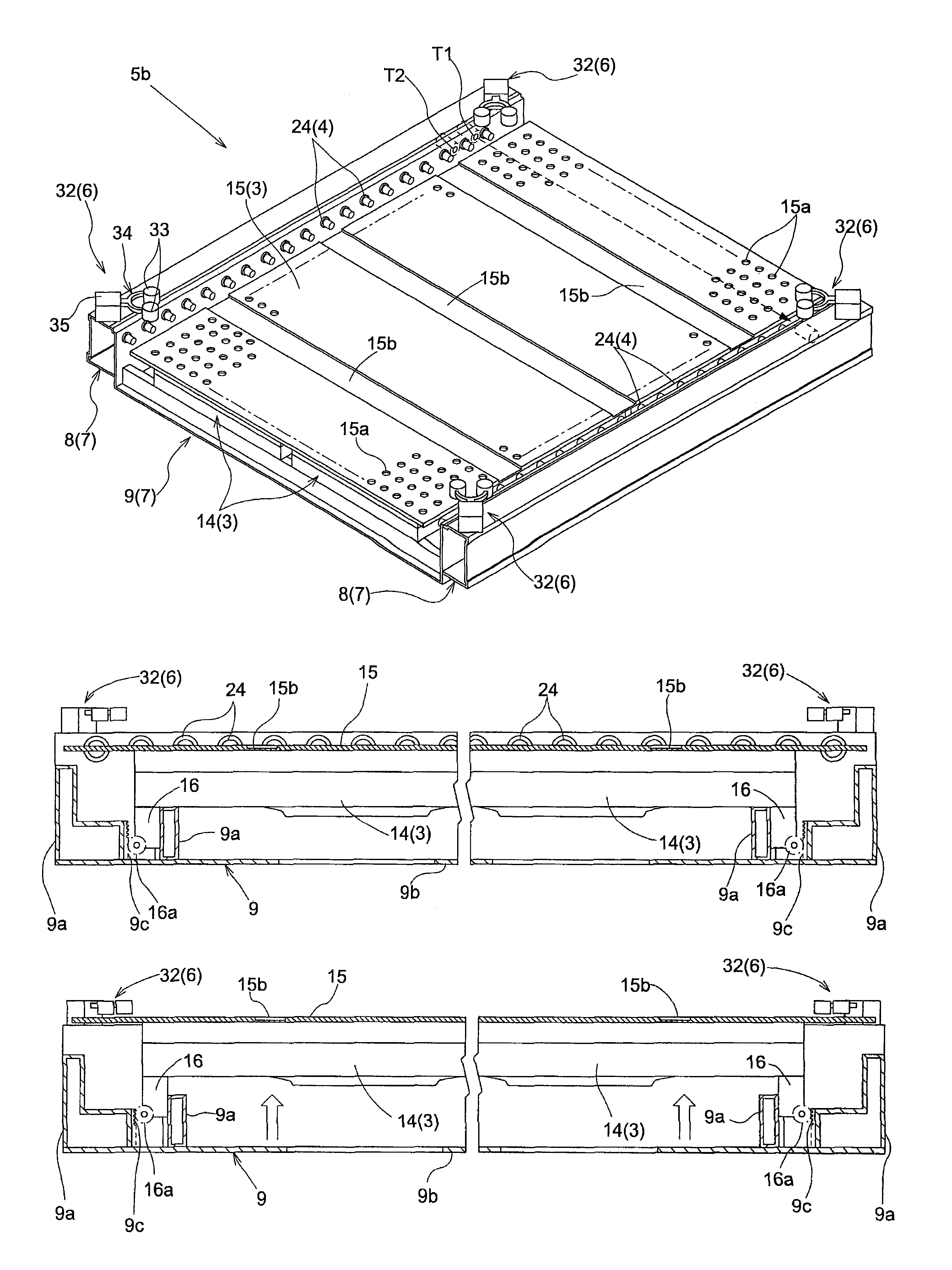
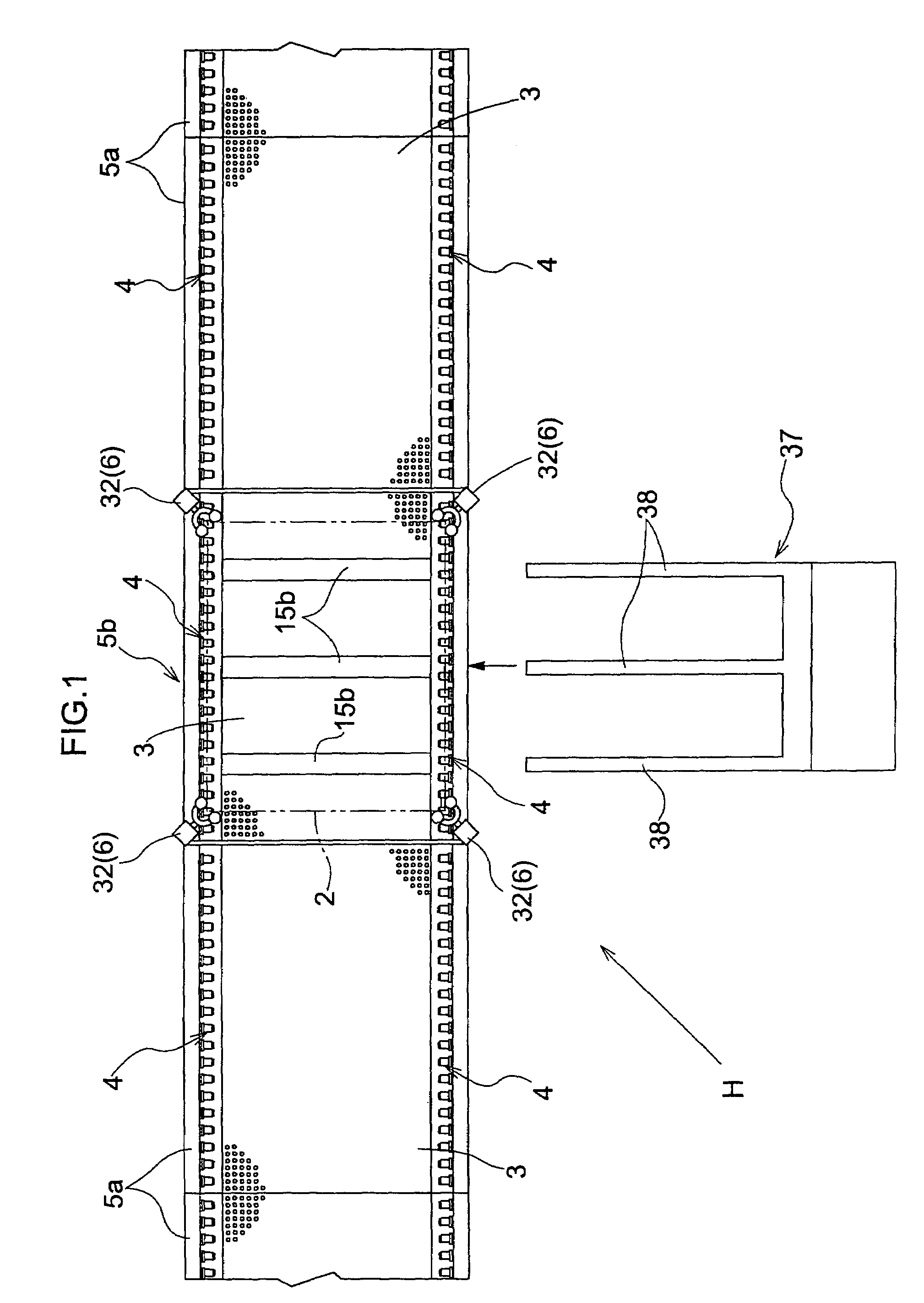
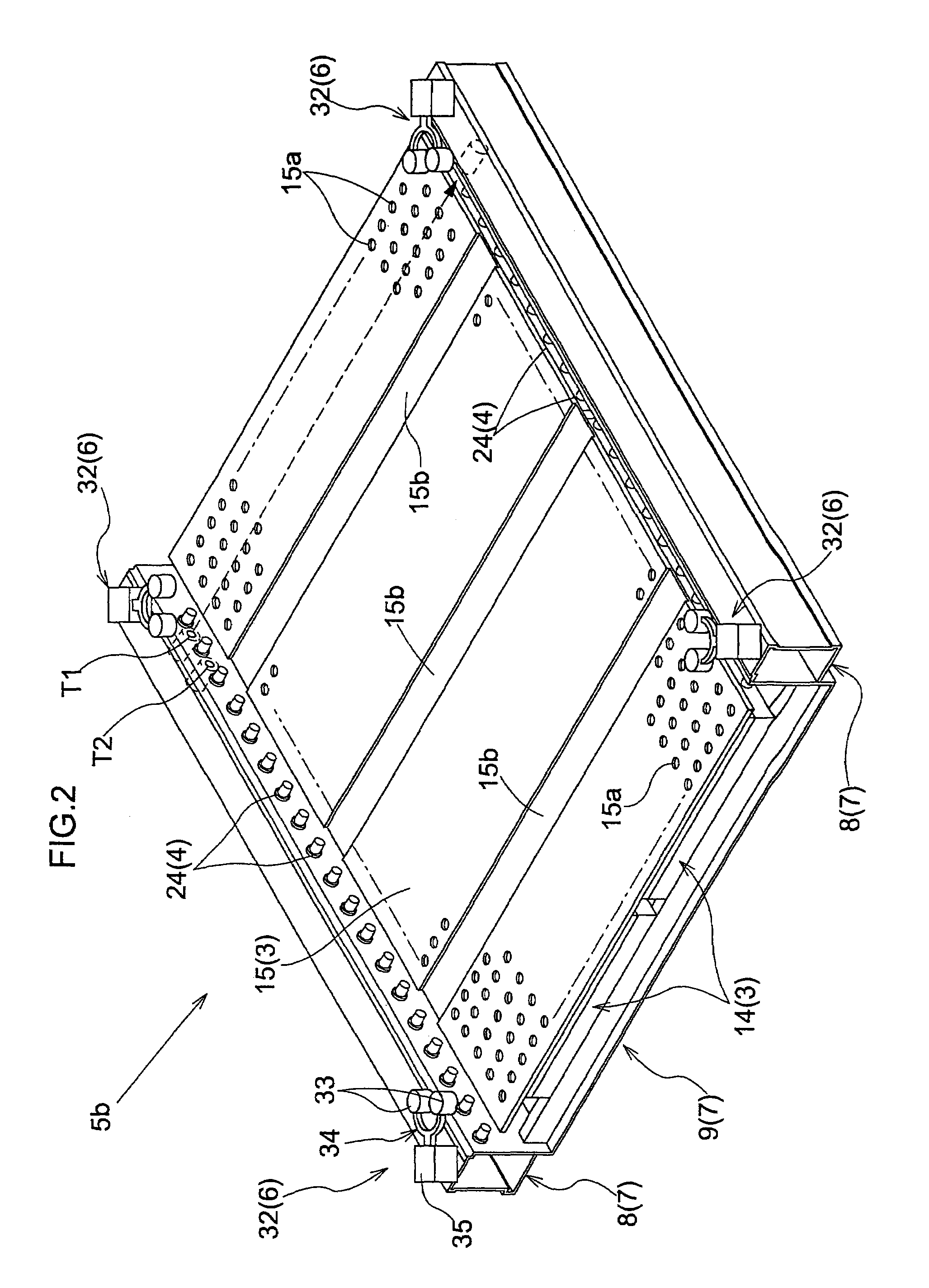
[0025]As shown in FIG. 1, a transporting apparatus H is provided with main transport members 5a that are capable of transporting a glass substrate 2 in the transporting direction and a transfer transport member 5b that is positioned side by side with the main transport members 5a in the transporting direction and that is capable of transporting the glass substrate 2 to and from the main transport members 5a. Also, in the transfer transport member 5b, the transporting apparatus H is provided with a transfer means 37 for performing a scooping task of scooping up the glass substrate 2 that is supported by a air-supplying-type support means 3 and a lowering task of lowering the glass substrate 2 so that it is supported by the air-supplying-type support means 3 of the tran...

second embodiment

[0057]The second embodiment illustrates a separate implementation from that of the first embodiment of how the drive force application means 4 and the air-supplying-type support means 3 provided in the transfer transport member 5b are raised and lowered relative to one another, and the following description based on the drawings focuses on this aspect. It should be noted that structural elements that are the same as those of the first embodiment are assigned the same reference numerals as in the first embodiment, and description thereof is omitted.

[0058]As shown in FIG. 12, one of the pair of accommodation frames 8 is supported by the unit frame member 9 in such a manner that it can move up and down freely. That is, an electric frame motor 31 for raising and lowering that accommodation frame 8 is provided in a lower portion of that accommodation frame 8, and an output gear 31a of the frame motor 31 meshes with a gear groove 9c formed in the lateral surface of a support frame portion...


PUM


Abstract

The invention discloses a transporting apparatus having a transport member provided with a air-supplying-type support portion for supplying purified air toward a lower surface of a transported object to contactlessly support the transported object, and a drive force application portion for contacting a lower surface of the transported object that is supported by the air-supplying-type support means and applying a drive force in the transporting direction to the transported object. The transporting apparatus, by raising and lowering the drive force application portion and the air-supplying-type support portion relative to one another, can be switched between a transport state where the drive force application portion is brought into contact with the lower surface of the transported object, and a transfer state where the drive force application portion is moved downward away from the transported object that is supported by the air-supplying-type support portion. The transporting apparatus is provided with a loading portion that can receive and support the transported object and that can be moved in a horizontal direction that intersects the transporting direction and in the vertical direction. The loading portion, in the transfer state, can be inserted in the horizontal direction into the space below the transported object.

Description

BACKGROUND OF THE INVENTION[0001]The present invention relates to transporting apparatuses provided with a transport member that is furnished with a air-supplying-type support means for supplying purified air toward a lower surface of a transported object to contactlessly support the transported object in a horizontal orientation or a substantially horizontal orientation, and a drive force application means that comes into contact with the lower surface of the transported object that is supported by the air-supplying-type support means and applies a drive force in the transporting direction to the transported object.[0002]In such transporting apparatuses, the air-supplying-type support means contactlessly supports the transported object and the drive force application means applies a drive force in the transporting direction to the transported object in a contacting manner. For example, in a case where a glass substrate for a liquid crystal is transported as the transported object, ...

Claims


Application Information

Patent Timeline
Patent Type & Authority Patents(United States)
IPC IPC(8): B65G35/00B65G47/29B65G49/00B65G51/03B65G49/02B65G49/06B65G49/07B65G53/08H01L21/677H01L21/68
CPCB65G49/065B65G49/064H01L21/677B65G2201/0214B65G2207/26
Inventor IKEHATA, YOSHITERUONO, TAKAYOSHIMORIMOTO, YUICHI
Owner DAIFUKU CO LTD
Why Eureka
Try Eureka