Wall-flow redistributor for packed columns

a technology of wall-flow redistributor and column, which is applied in the direction of combustion-air/fuel-air treatment, separation process, lighting and heating apparatus, etc., can solve the problems of poor mass/heat transfer efficiency, accumulation of liquid on the wall or near-wall region of the packing, and inefficiency of this approach

Inactive Publication Date: 2006-03-07
AIR PROD & CHEM INC
View PDF25 Cites 13 Cited by
  • Summary
  • Abstract
  • Description
  • Claims
  • Application Information

AI Technical Summary

Benefits of technology

[0099]Some of the benefits and advantages of the redistributors of the present invention are:
[0100]i. Capture the liquid on the wall of the column or the wall-region of the structured packing and redistribute the liquid far into the interior of the packing, away from the column wall.

Problems solved by technology

Maldistribution of liquid in packed two-phase mass / heat transfer columns has long been recognized as leading to poor mass / heat transfer efficiency.
However, as taught in U.S. Pat. No. 6,286,818 B1 (Buhmann), these conventional designs still result in accumulation of liquid on the wall or near-wall region of the packing.
Applicants believe that the inefficiency of this approach lies in the fact that the liquid re-introduced to the packing from the wall or near-wall region enters the packing at the outer periphery, and will just as likely flow back toward the wall / near-wall region as flow toward the center of the column.
This approach is penalized by the increased cost for tooling and special handling of each sheet of structured packing, as well as the increased assembly costs associated with the individual segments (or “bricks”) of structured packing which must necessarily be assembled with the specific orientation mandated by the edge modification.
The devices tend to be large and include many massive parts, and thus incur large manufacturing costs and the added costs associated with additional column height.
The cost associated with the column height required to get uniform liquid flow across the column cross-section from the secondary distributor and to accommodate the pre-distributor is very significant.
Furthermore, manufacturing and installation costs for this type of design also are high.
There is no pre-distributor, and no special means for mixing liquid captured from the wall with the rest of the captured liquid.
The main drawback of these approaches is that they do not specifically address the maldistribution associated with the column wall / packing periphery.
Both of these approaches attempt to address liquid maldistribution by changing the characteristics of the structured packing within the column, but no special provisions are made to address the predominance of liquid on the wall of the column or in the near-wall region of the packing.
A disadvantage of this approach is that it introduces additional pressure drop into the vapor phase as it passes through the high density (flooded) packing.

Method used


Image

  • Wall-flow redistributor for packed columns
  • Wall-flow redistributor for packed columns
  • Wall-flow redistributor for packed columns

Examples


Embodiment Construction

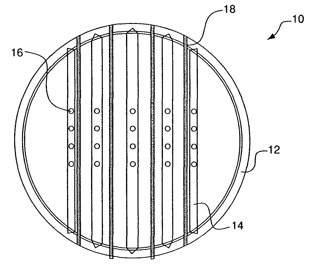
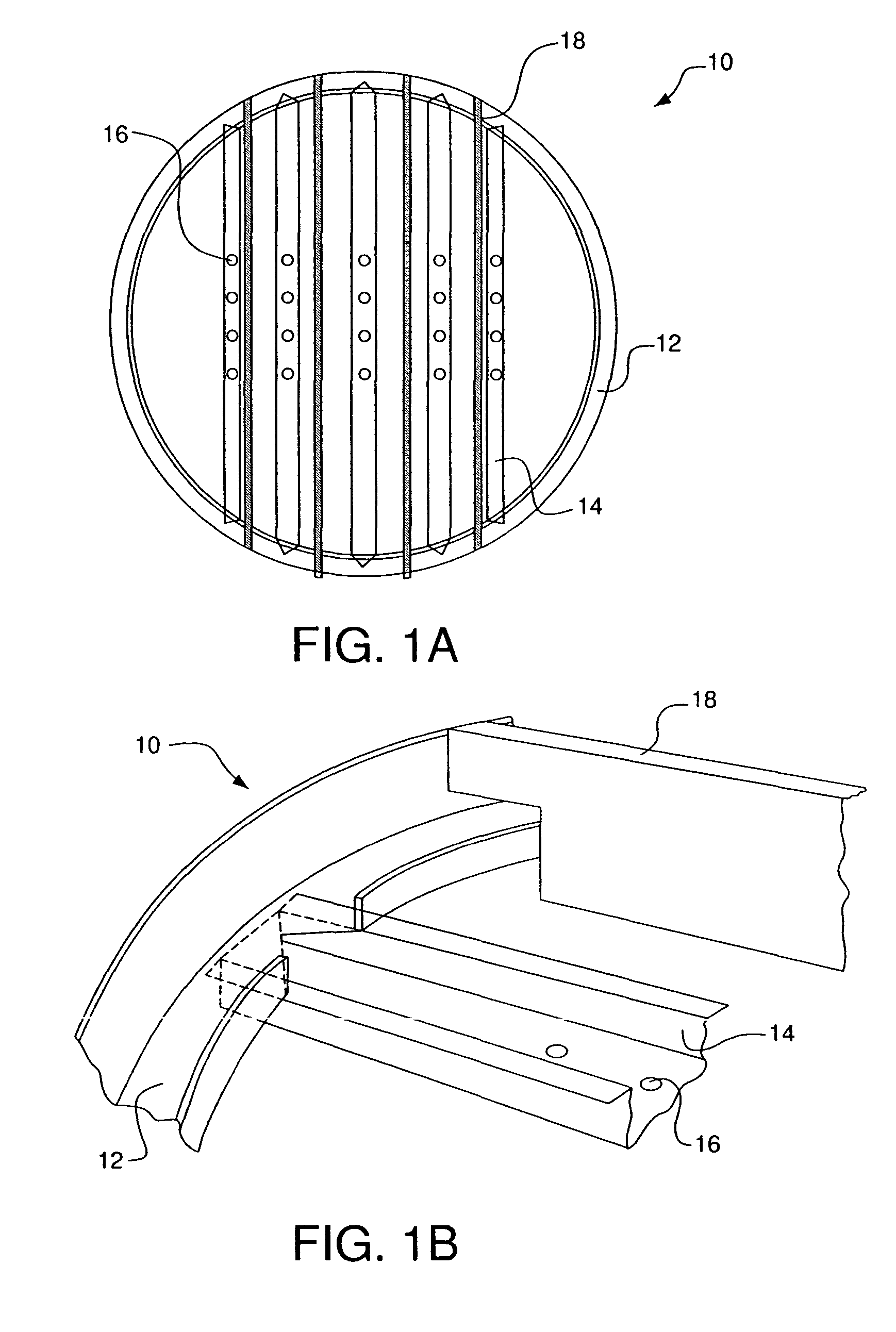
[0071]The present invention addresses the need to collect descending liquid from the column wall and / or near-wall region in the packed section of an exchange column and to redistribute that liquid toward the center of the column (i.e., away from the wall). The present invention achieves such liquid redistribution without incurring high manufacturing costs and / or significant costs associated with additional column height.

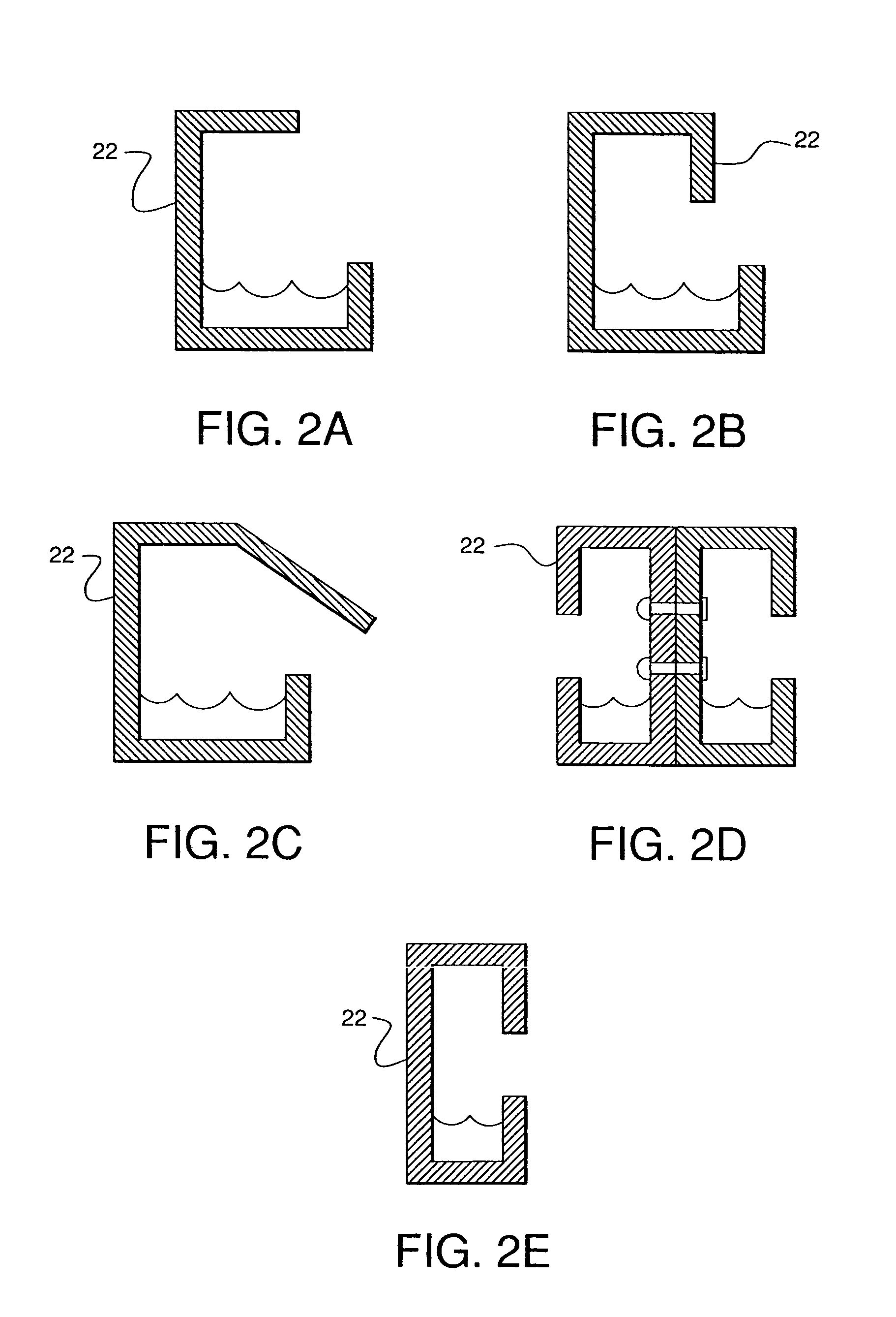
[0072]The redistributor of the present invention removes liquid from the column wall and from the packing in a zone near the column wall and transports the liquid farther into the center of the column than the existing wiper designs. The height of the redistributor is relatively modest—about 100 mm at most. Although the redistributor reduces the gross liquid maldistribution in the column by redirecting liquid flowing on the wall toward the center of the column, the redistributor is not intended to approach the degree of uniformity achieved by standard liquid distribu...


PUM

PropertyMeasurementUnit
heightaaaaaaaaaa
widthaaaaaaaaaa
heightaaaaaaaaaa

Abstract

An apparatus for collecting and redistributing a flow of a liquid descending in an exchange column containing a layer of structured packing and having a longitudinal axis, a cross-sectional area, and an inner wall having an inner perimeter, includes: a wall-flow collector located above the layer of structured packing, the wall-flow collector having an outer perimeter adjacent the inner perimeter of the inner wall and being adapted to collect at least a portion of the liquid descending on or near the inner wall of the exchange column; a transmission means for transmitting at least a portion of the collected liquid collected by the wall-flow collector toward the longitudinal axis a substantial distance across the cross-sectional area of the exchange column; and a dispensing means for dispensing at least a portion of the portion of the collected liquid from the transmission means to the layer of structured packing.

Description

BACKGROUND OF THE INVENTION[0001]The present invention relates to an apparatus and a method for collecting and redistributing a flow of a descending liquid to a structured packing in an exchange column for heat and / or mass transfer processes. The apparatus and method have particular application in cryogenic air separation processes utilizing distillation, although the apparatus and method may be used in other heat and / or mass transfer processes. The present invention also relates to methods for assembling an apparatus for collecting and redistributing a flow of a descending liquid to a structured packing in an exchange column used in such processes.[0002]The term “column”, as used herein, means a distillation or fractionation column or zone, i.e., a column or zone wherein liquid and vapor phases are countercurrently contacted to effect separation of a fluid mixture, such as by contacting of the vapor and liquid phases on packing elements or on a series of vertically-spaced trays or ...

Claims


Application Information

Patent Timeline
Patent Type & Authority Patents(United States)
IPC IPC(8): B01F3/04F28F25/04B01D3/00B01D3/20B01D3/22B01D3/32B01D53/18B01J10/00B01J19/32
CPCB01D3/008B01D3/20B01D3/205F25J3/04927B01D53/185B01J19/325F25J3/04763B01D3/326B01D3/22B01J19/32
Inventor ARMSTRONG, PHILLIP ANDREWHOUGHTON, PATRICK ALANMEEHAN, JAMES WILLIAMMESKI, GEORGE AMIR
Owner AIR PROD & CHEM INC
Why Eureka
Try Eureka