Retractable panel interface cable device and method

a technology of interface cable and retractable panel, which is applied in the direction of coupling device connection, aircraft crew accommodation, transportation and packaging, etc., can solve the problems of reducing the access location of modules, increasing the difficulty of installation and maintenance, and significant risk of aircraft wiring damage or failure, so as to facilitate access to equipment and prevent damage or failure of communication lines

Inactive Publication Date: 2006-03-07
GARMIN INT
View PDF25 Cites 14 Cited by
  • Summary
  • Abstract
  • Description
  • Claims
  • Application Information

AI Technical Summary

Benefits of technology

[0011]The above mentioned problems with access and repair or replacement of avionic equipment are addressed by the present invention and will be understood by reading and studying the following specification. Systems, devices and methods are provided for mounting various configurations of avionic equipment. The systems, devices, and methods of the present invention offer easier access to equipment while at the same time maintaining secure mounting to prevent damage or failure of communication lines.

Problems solved by technology

Reduced access locations for modules are increasing the difficultly in installation and maintenance.
Because an electrical failure during flight places the aircraft and lives of its passengers at serious risk, extra safety precautions are necessary to protect against electrical failure.
In particular, vibration of aircraft during flight gives rise to a significant risk to damage or failure of aircraft wiring.
One problem with this approach has been that any re-wiring work required the cutting of numerous cable ties, and the re-fastening of the cable ties after work is completed.

Method used


Image

  • Retractable panel interface cable device and method
  • Retractable panel interface cable device and method
  • Retractable panel interface cable device and method

Examples


Embodiment Construction

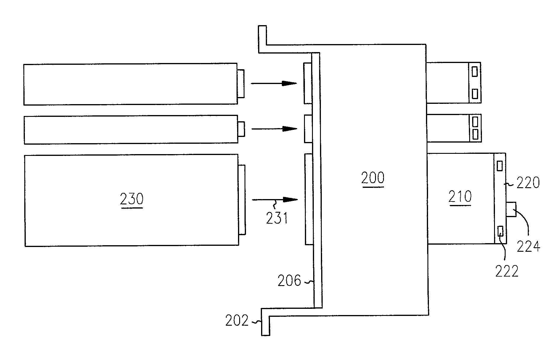
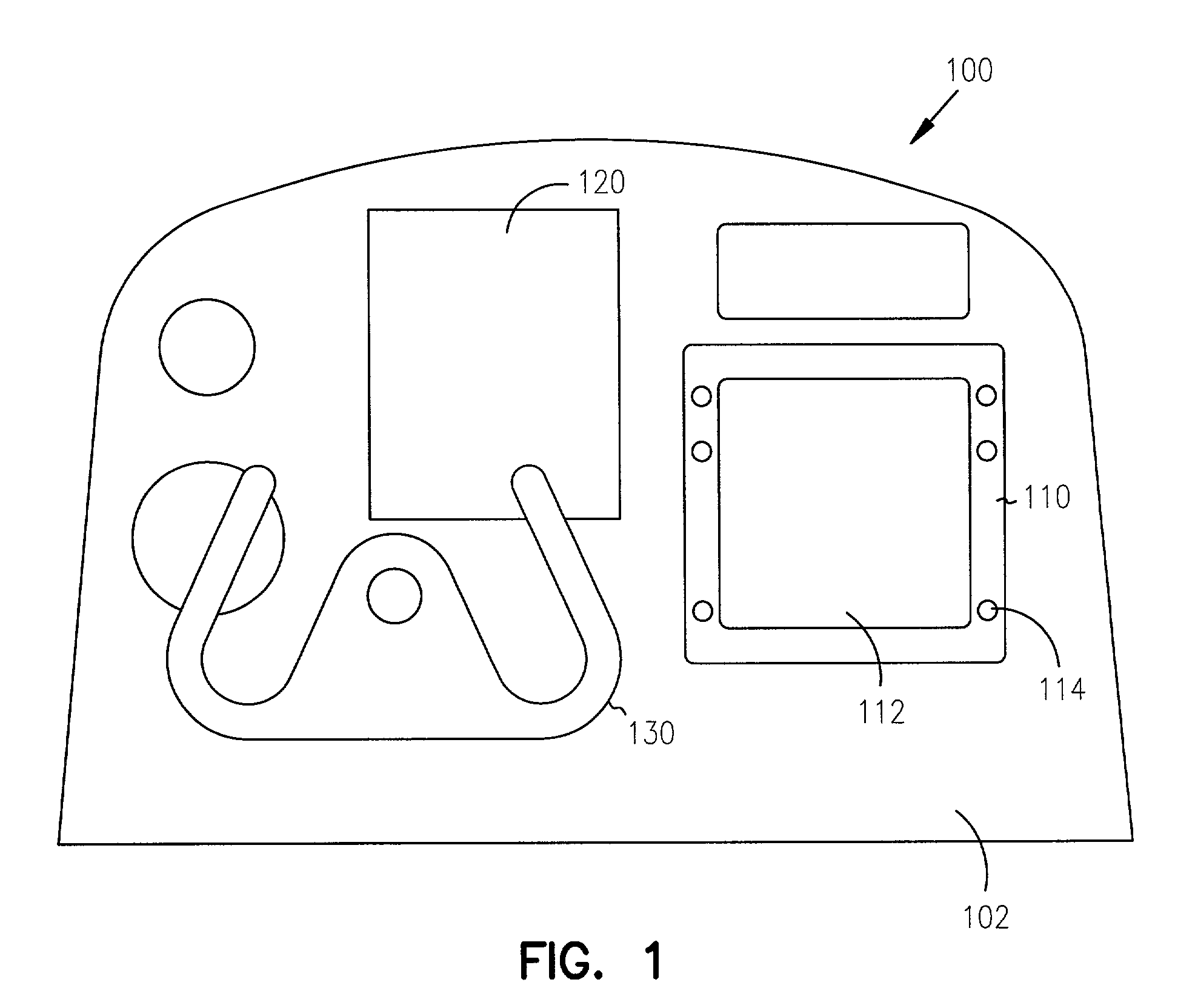
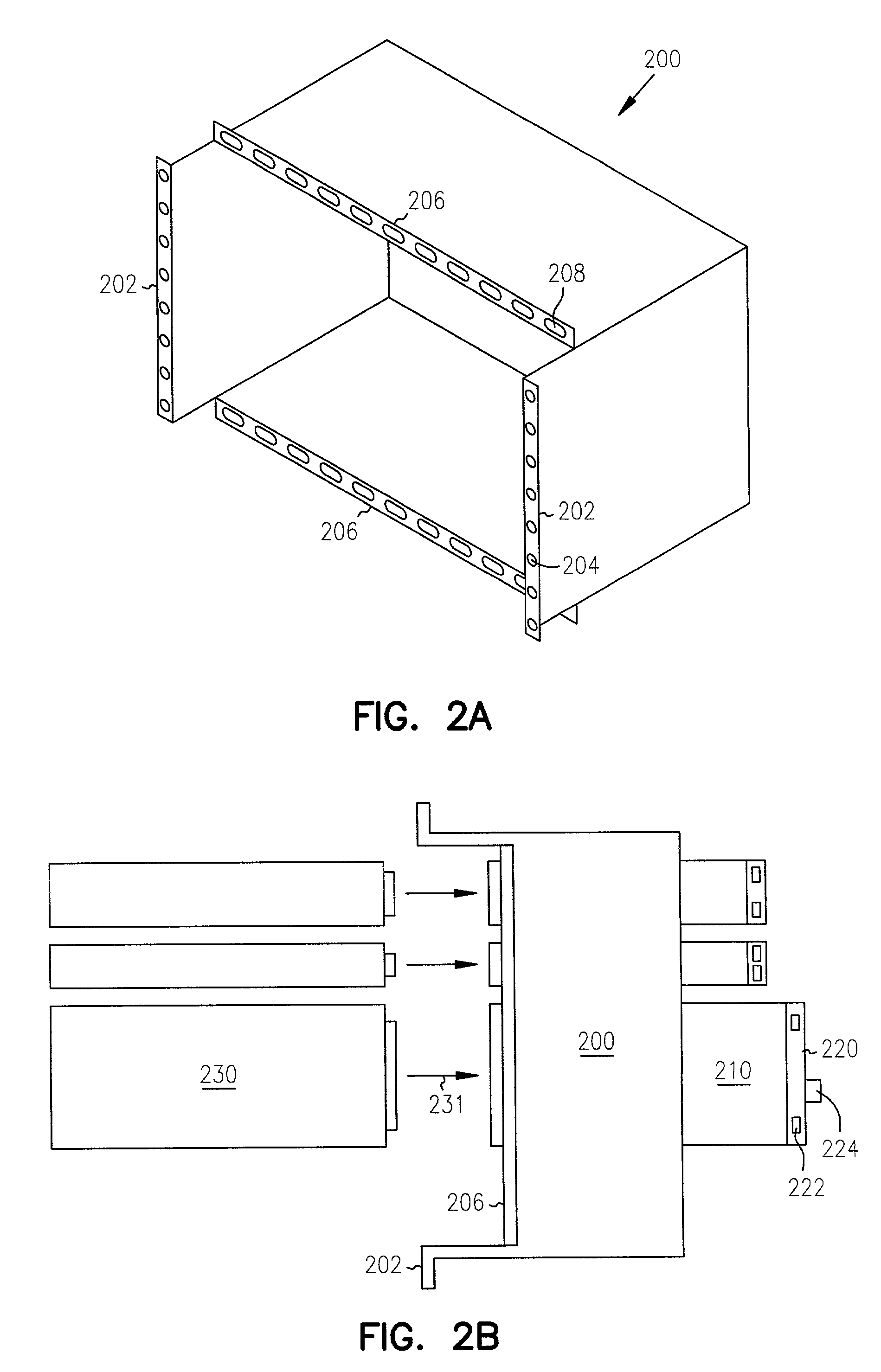
[0026]In the following detailed description of the invention, reference is made to the accompanying drawings which form a part hereof, and in which is shown, by way of illustration, specific embodiments in which the invention may be practiced. In the drawings, like numerals describe substantially similar components throughout the several views. These embodiments are described in sufficient detail to enable those skilled in the art to practice the invention. Other embodiments may be utilized and structural, logical, and electrical changes may be made without departing from the scope of the present invention.

[0027]References to directions, such as up, down, above, or below, etc. will have their normal meaning with the ground being downward when referring to embodiments not used in aircraft. When referring to embodiments mounted to an aircraft, downwards will refer to the direction towards a bottom surface of the airplane, regardless of the orientation of the airplane during flight. Wh...


PUM


Abstract

A device and method for mounting and wiring avionic equipment such as modules and display units in an aircraft is provided. The novel configuration utilizes a flexible guide that routes communication lines from a device such as a display unit to other devices such as avionic modules. Because the flexible guide is only allowed motion in substantially a two dimensional plane, the communication lines routed by the flexible guide are held securely in place before, during, and after any access procedure. Damage or failure of communication lines is prevented by the structural support of the flexible guide, while at the same time, the display unit may be easily removed to allow access to devices such as modules located behind.

Description

CROSS-REFERENCE TO RELATED APPLICATIONS[0001]This application is related to the following co-pending, commonly assigned U.S. patent applications: “Slide-in Connector Plate for Avionic Unit Rack,” Ser. No. 10 / 086,568, “Electronic Equipment Module Mounting Apparatus and Method,” Ser. No. 10 / 086,482, “System and Method for Mounting Units for an Avionic Display,” Ser. No. 10 / 086,483, “Electronic Equipment Module Apparatus and Method,” each of which the disclosure is herein incorporated by reference in its entirety.FIELD OF THE INVENTION[0002]The invention relates to mounting devices and methods routing communication lines between devices. Specifically, this invention relates to mounting devices and methods of routing communication lines for avionic equipment in an aircraft.BACKGROUND OF THE INVENTION[0003]In aviation, there is an increasing presence of computerized and electronic equipment for applications such as instrumentation and navigation. The term avionics refers generally to ele...

Claims


Application Information

Patent Timeline
Patent Type & Authority Patents(United States)
IPC IPC(8): H01R33/00
CPCH05K7/1421
Inventor RUFF, BRIAN F.ROLSTON, WALTER J.WHEATON, SHELDON T.
Owner GARMIN INT
Why Eureka
Try Eureka