Oil supply system for engine

a technology for oil supply systems and engines, applied in the direction of machines/engines, liquid fuel engines, auxilaries, etc., can solve the problems of increasing the so-called oil leakage, difficult to keep the required oil amount, and frequent oil leakage phenomenon

Active Publication Date: 2006-03-14
AISIN SEIKI KK
View PDF9 Cites 27 Cited by
  • Summary
  • Abstract
  • Description
  • Claims
  • Application Information

AI Technical Summary

Problems solved by technology

This will cause the increase of so-called oil leakage.
That is, viscosity of the hydraulic oil becomes more less in response to further increase of the rotational speed of the rotor, and an oil leakage phenomenon may occur frequently.
In order to prevent this, however, there is a problem that it is difficult to keep the required oil amount for keeping the hydraulic pressure for a jet for a piston and a crank journal in the hydraulic-oil receiving unit.

Method used


Image

  • Oil supply system for engine
  • Oil supply system for engine
  • Oil supply system for engine

Examples


Embodiment Construction

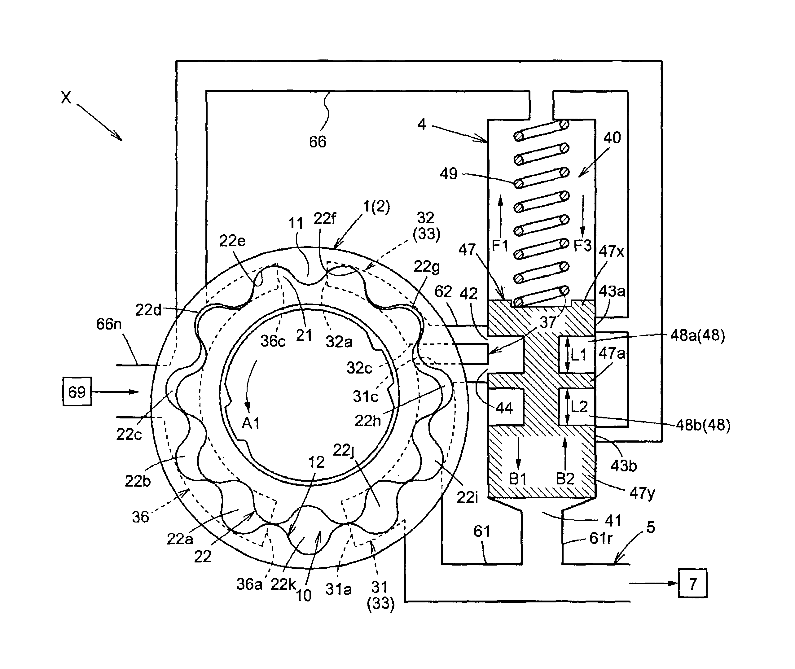
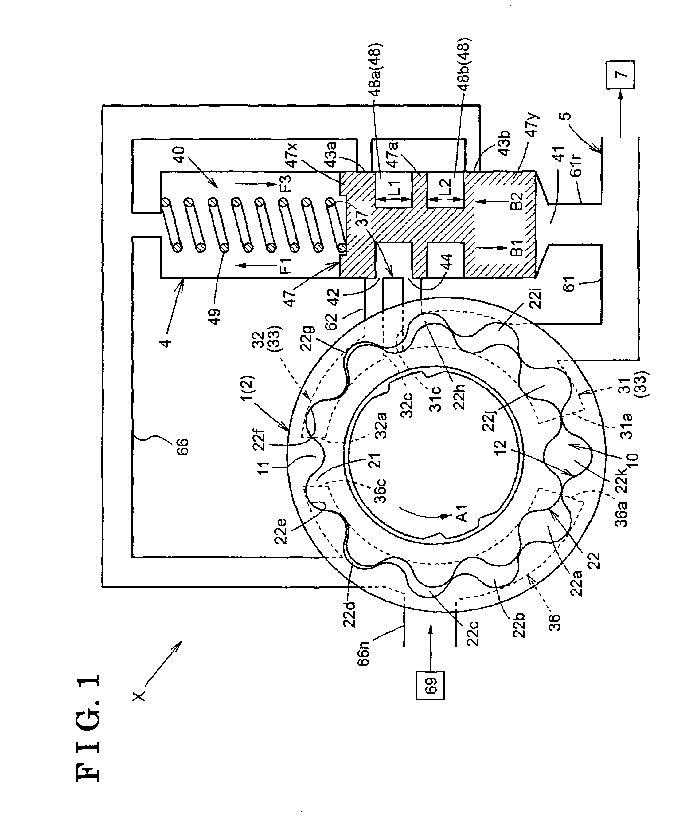
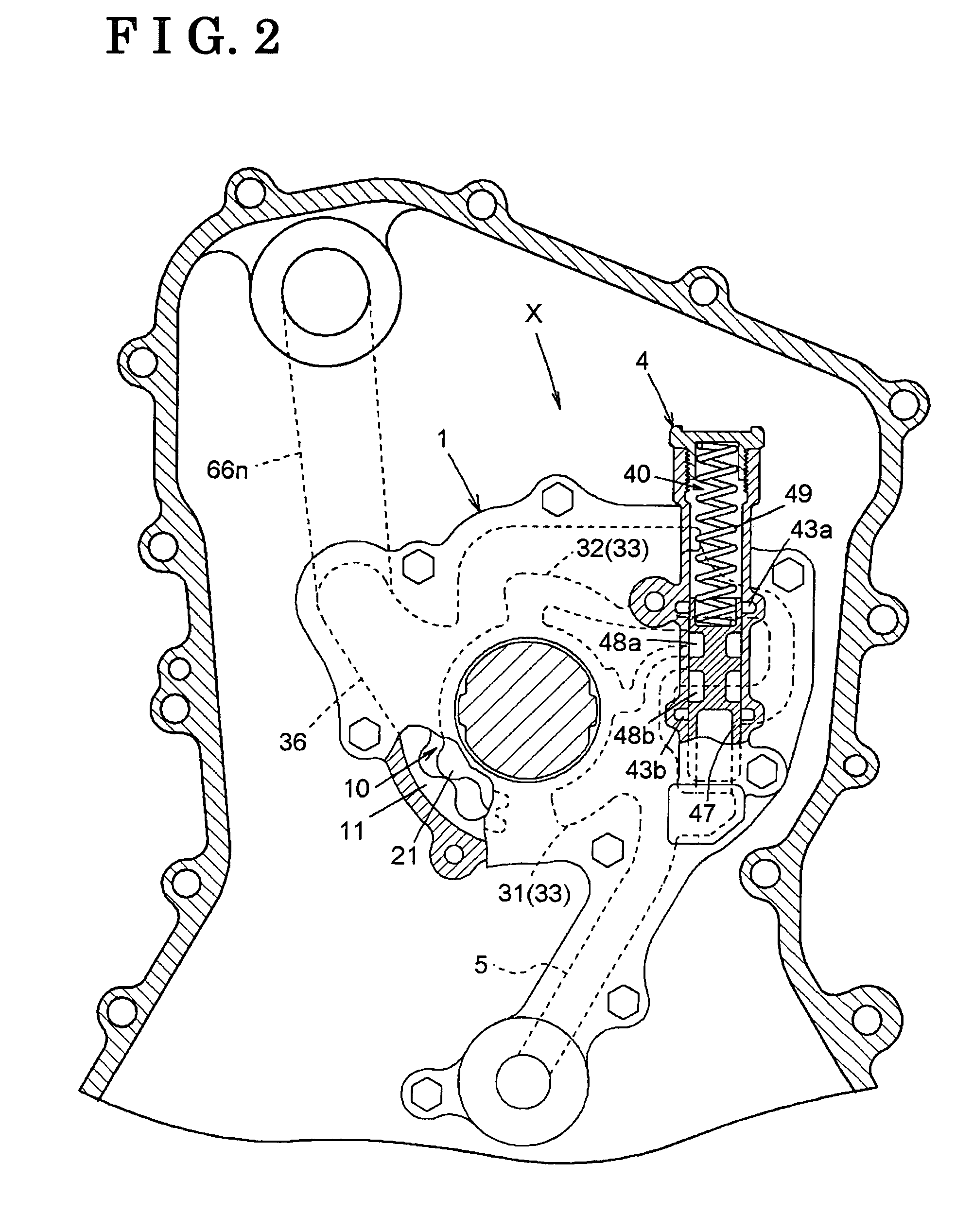
[0027]The present invention is described in further detail below with reference to an embodiment according to the accompanying drawings. This embodiment illustrates an oil supply system which generates hydraulic pressure by the rotation of a crankshaft in an internal combustion engine mounted in a vehicle. FIG. 1 is a conceptual arrangement of an oil supply system of this embodiment of the present invention. FIG. 2 is a schematic layout of the oil supply system of the present invention mounted in the engine.

[0028]As illustrated in FIGS. 1 and 2, the oil supply system X for the engine of the present invention is provided with a pump body 1 including an inlet port 36 suctioning a hydraulic oil in response to the rotation of a rotor 2 driven by synchronizing with a crankshaft, a first outlet port 31 discharging the hydraulic oil and a second outlet port 32 discharging the hydraulic oil therefrom. The oil supply system X for the engine is further provided with a hydraulic-oil-delivery p...


PUM


Abstract

An oil supply system for an engine includes a pump body provided with a first outlet port and a second outlet port. The oil supply system further includes a hydraulic-oil-delivery passage, a first oil passage, a second oil passage and a return hydraulic passage. The valve body divides a hydraulic-oil receiving portion for receiving the hydraulic oil in the hydraulic-pressure control valve chamber into a first valve chamber and a second valve chamber. When the hydraulic pressure oil delivered to the hydraulic-oil-delivery passage is in a predetermined value, the hydraulic oil discharged out of the second outlet port is delivered to the hydraulic-oil-delivery passage via the first valve chamber. When the hydraulic pressure delivered to the hydraulic-oil-delivery passage exceeds the predetermined value, the hydraulic oil discharged out of the second outlet port is delivered to the hydraulic-oil-delivery passage via the second valve chamber.

Description

CROSS REFERENCE TO RELATED APPLICATIONS[0001]This application is based on and claims priority under 35 U.S.C. § 119 with respect to Japanese Patent Application 2003-377530, filed on Nov. 6, 2003, the entire content of which is incorporated herein by reference.FIELD OF THE INVENTION[0002]This invention generally relates to an oil supply system for an engine. More specifically, this invention relates to an oil supply system for an engine provided with a pump body including an inlet port suctioning hydraulic oil in response to the rotation of a rotor driven by synchronizing with a crankshaft and first and second outlet ports discharging the hydraulic oil in response to the rotation of the rotor. The oil supply system for the engine is further provided with a hydraulic-oil-delivery passage for delivering the hydraulic oil to a hydraulic-oil receiving unit, a first oil passage for delivering the hydraulic oil discharged out of at least the first outlet port to the hydraulic-oil-delivery ...

Claims


Application Information

Patent Timeline
Patent Type & Authority Patents(United States)
IPC IPC(8): F01M1/00F04C2/10F04C14/06F01M1/16F04C14/12F04C14/24F04C15/00
CPCF04C14/065F04C15/0092F04C14/24F04C14/12F04C2/10
Inventor ONO, HISASHIKATO, HIROSHI
Owner AISIN SEIKI KK
Why Eureka
Try Eureka