Die down multi-media card and method of making same

a multi-media card and die-down technology, applied in the field of memory cards, can solve the problems of adding weight, thickness, stiffness and complexity of modules, and sometimes causing structural deficiencies or problems in molding or encapsulation processes

Inactive Publication Date: 2006-03-14
AMKOR TECH SINGAPORE HLDG PTE LTD
View PDF36 Cites 18 Cited by
  • Summary
  • Abstract
  • Description
  • Claims
  • Application Information

AI Technical Summary

Benefits of technology

[0009]A memory card constructed in accordance with the present invention may be assembled by attaching a lid or skin to the above-described circuit module. The presentation of the semiconductor die of the circuit module in a die down configuration eliminates various drawbacks associated with current memory card manufacturing methodologies and, most notably, unwanted exposure of the die pad within the memory card. In an alternative embodiment of the present invention, the body may be formed in a manner eliminating the need to include a separate lid or skin. In this regard, the body is formed having a shape which satisfies any one of various form factor requirements for a memory card format. The body of the circuit module or memory card may be formed via an injection molding technique, reaction injection molding, resin transfer molding, or infusion molding through the use of a dedicated mold having a circuit module placed therein. The use of such dedicated mold also alleviates various problems currently encountered with memory card manufacturing processes, including chipping within the body and mold gate pull-out.

Problems solved by technology

The dies are interconnected using a circuit board substrate which adds to the weight, thickness, stiffness and complexity of the module.
It has been found that the molding or encapsulation process sometimes gives rise to structural deficiencies or problems within the resultant memory card.
These problems include portions of the die pad of the leadframe being exposed within the memory card, flash being disposed on the contacts of the leadframe, chipping in a peripheral flange area of the body, and mold gate pull-out wherein a portion of the mold or encapsulating compound is pulled out from within the body leaving a small recess or void therein.

Method used


Image

  • Die down multi-media card and method of making same
  • Die down multi-media card and method of making same
  • Die down multi-media card and method of making same

Examples


first embodiment

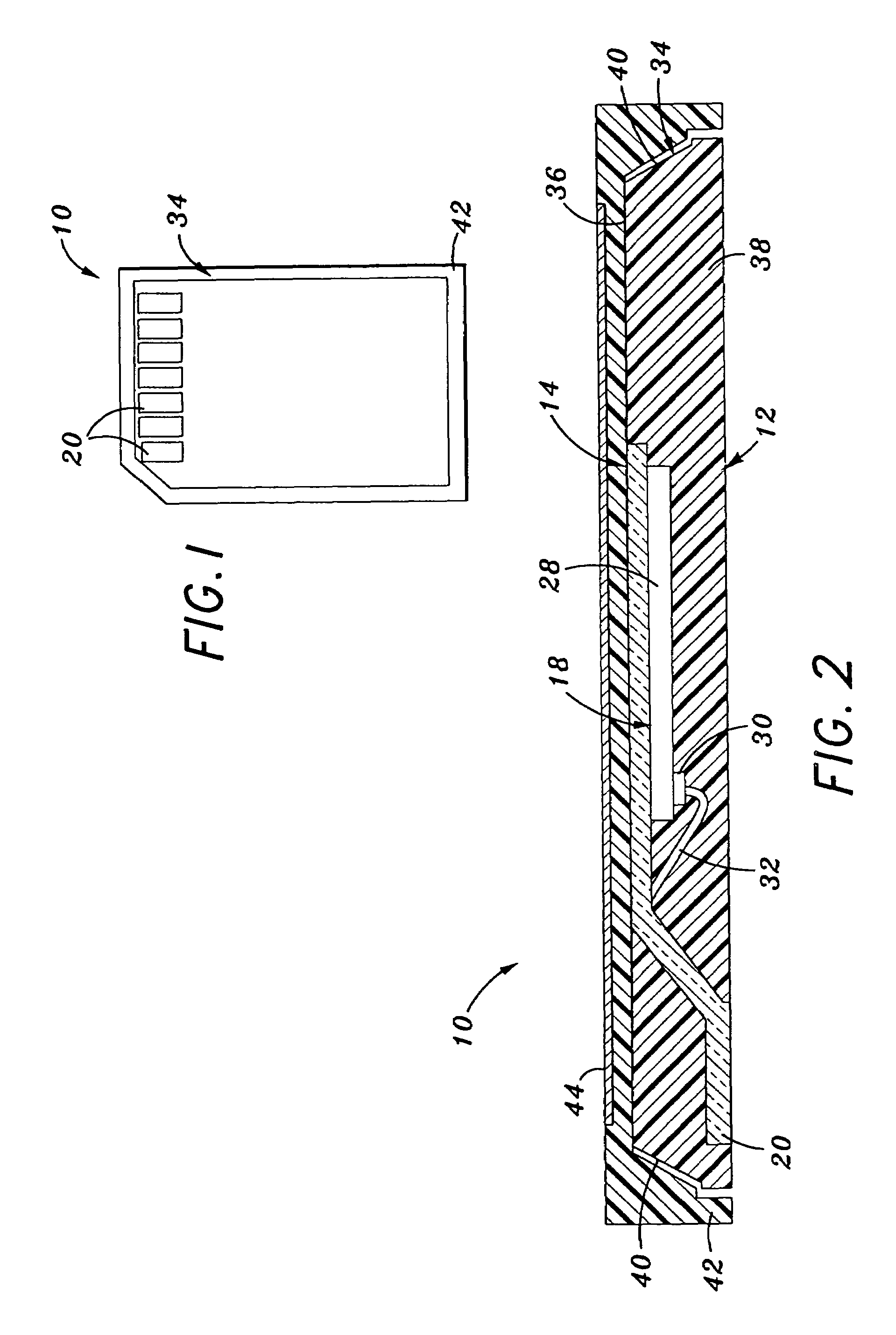
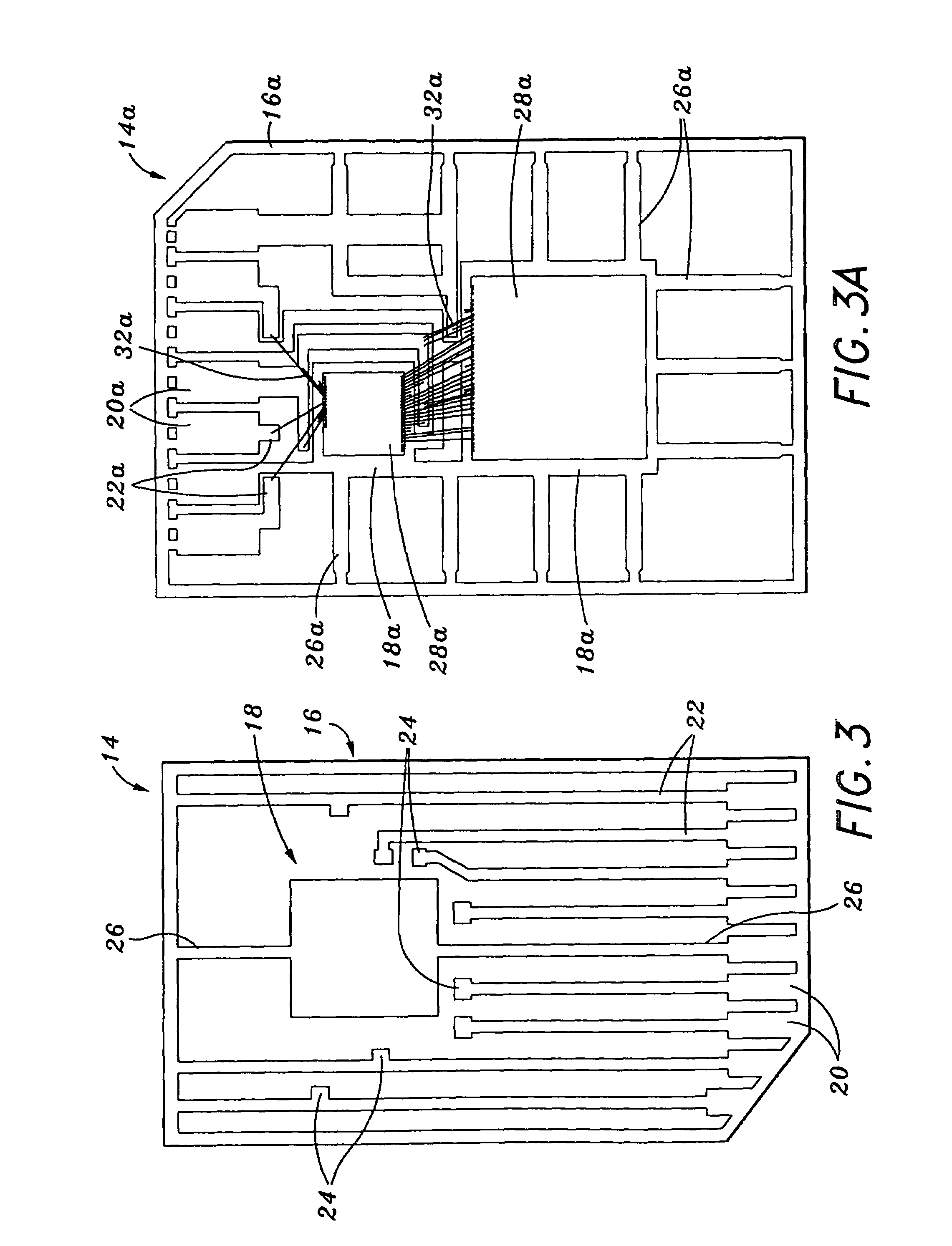
[0019]Referring now to the drawings wherein the showings are for purposes of illustrating preferred embodiments of the present invention only, and not for purposes of limiting the same, FIGS. 1 and 2 depict a memory card 10 constructed in accordance with the present invention. The memory card 10 includes a circuit module 12. The circuit module 12 itself includes a leadframe 14 which is shown in a preliminary, unbent state in FIG. 3 and in its final, bent state in FIG. 2. The particular structural attributes of the leadframe 14 will be described below. As shown in FIGS. 1 and 2, the memory card 10 including the circuit module 12 has a form factor particularly suited for use in a multi-media card memory application. However, those of ordinary skill in the art will recognize that the circuit module 12 of the present invention may also be used in alternative memory card formats including secure digital cards (SDC), compact flash (CF), memory stick, and other small form factor memory car...

second embodiment

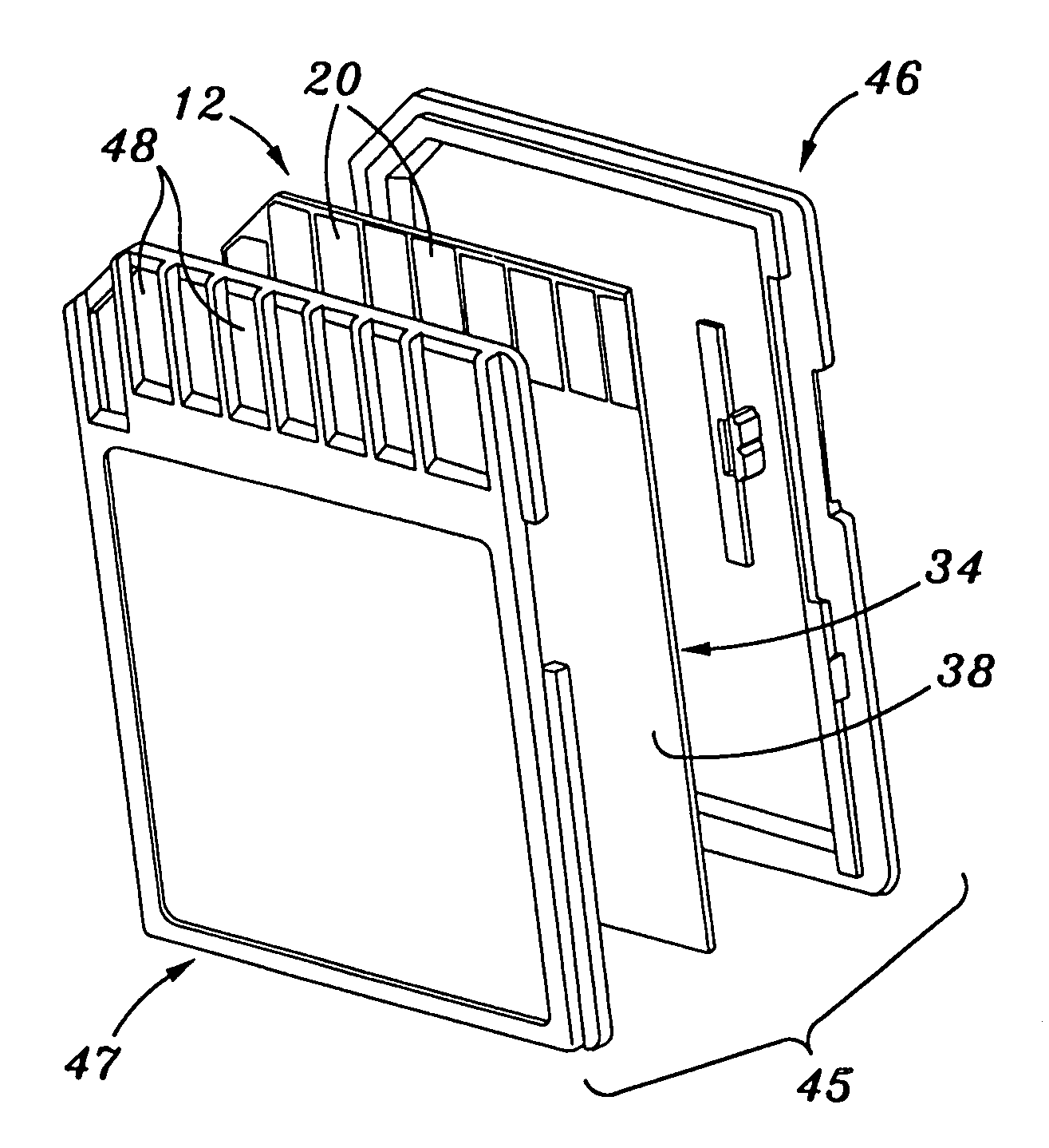
[0031]As indicated above, the memory card 10 has the form factor of a multi-media card. As also indicated above, the circuit module 12 may be employed in memory card format other than a multi-media card format. For example, as shown in FIG. 4, the circuit module 12 can be incorporated into a secure digital card 45 constructed in accordance with the present invention. In the secure digital card format, first and second skins 46, 47 are included, with the first, top skin 46 being attached to the circuit module 12 and covering approximately the upper half thereof, and the second, bottom skin 47 also being attached to the circuit module 12 and covering approximately the lower half thereof. The top and bottom skins 46, 47 are typically ultrasonically welded or otherwise adhered to each other, with the top skin 46 covering the top surface 36 of the body 34 and the bottom skin 47 covering the bottom surface 38 of the body 34. The bottom skin 47 is formed to include one or more windows 48 w...


PUM


Abstract

A circuit module comprising a leadframe having at least one die pad, a plurality of contacts, and a plurality of conductive traces extending from respective ones of the contacts toward the die pad. The traces are bent in a manner wherein the die pad and the contacts extend along respective ones of spaced, generally parallel frame planes. Attached to the die pad is a semiconductor die which extends along a die plane disposed between and generally parallel to the frame planes. The semiconductor die is electrically connected to at least one of the traces. A body at least partially encapsulates the leadframe and the semiconductor die such that the die pad is exposed within a top surface defined by the body and the contacts are exposed within a bottom surface defined by the body.

Description

CROSS-REFERENCE TO RELATED APPLICATIONS[0001]The present application is a continuation of U.S. patent application Ser. No. 10 / 266,329 entitled DIE DOWN MULTI-MEDIA CARD AND METHOD OF MAKING SAME filed Oct. 8, 2002, now U.S. Pat. No. 6,910,635.STATEMENT RE: FEDERALLY SPONSORED RESEARCH / DEVELOPMENT[0002](Not Applicable)BACKGROUND OF THE INVENTION[0003]The present invention relates generally to circuit modules and, more particularly, to a memory card (e.g., a multi-media card (MMC)) comprising a leadframe implanted into a plastic body such that a semiconductor die is mounted in a downward configuration with respect to the connector of the card.[0004]As is well known in the electronics industry, circuit modules or cards are being used in increasing numbers to provide memory storage and other electronic functions for devices such as digital cameras, MP3 players, cellular phones, and personal digital assistants. In this regard, circuit modules are currently used in various memory card for...

Claims


Application Information

Patent Timeline
Patent Type & Authority Patents(United States)
IPC IPC(8): G06K19/00G06K19/077
CPCG06K19/077G06K19/07732H01L2224/48091H01L2224/48247H01L2924/3025H01L2924/00014
Inventor MIKS, JEFFREY ALANMIRANDA, JOHN A.
Owner AMKOR TECH SINGAPORE HLDG PTE LTD
Why Eureka
Try Eureka