Sheet feeder and image forming apparatus having the same

a technology of feeder and image forming apparatus, which is applied in the direction of thin material processing, article separation, printing, etc., can solve the problems of limited number of sheets that can be loaded on the feed tray, and the inability to achieve sheet separation, so as to achieve the effect of further improving the sheet separating action

Inactive Publication Date: 2006-03-14
BROTHER KOGYO KK
View PDF21 Cites 7 Cited by
  • Summary
  • Abstract
  • Description
  • Claims
  • Application Information

AI Technical Summary

Benefits of technology

[0013]With this structure, when weak or soft sheets are fed from the sheet holder, a leading edge of a topmost sheet of the stack slides over the inclined separating surface with a small rotation force of the sheet feed roller. Thus, the topmost sheet can be applied with the sheet separating action. Accordingly, the movable support plate does not need to retract below the upper surface of the sheet holder. When rigid or strong sheets are fed from the sheet holder, the leading edges of the sheets held by the sheet holder are surely received by the inclined separating surface. Therefore, the rotation force of the sheet feed roller becomes strong, so that the force to press the movable support plate from the sheet feed roller becomes large. Thus, the movable support plate retracts below the sheet holder against the urging force from the urging member. At that time, the topmost sheet warps along a space formed between the topmost sheet and the rest of sheets, which backwardly deform, at its lower part between the leading edge of the topmost sheet and a portion near the connection of the movable support plate and the fixed support plate, so that the inclined angle of the leading edge of the topmost sheet to the inclined separating surface becomes more acute. Because of this, it is easy to slide the leading edge of the topmost sheet over the inclined separating surface, and the sheet can be separated one by one from the stack of sheets. The degree of the inclination of the movable support plate can be changed in accordance with the rigidity of the sheets and degree of the rotation force of the sheet feed roller. With this structure, the sheet separating action can be further improved, and thus, a paper jam, such as a multi-feed problem, can be prevented.

Problems solved by technology

Because of this structure, a maximum number of sheets that can be loaded on the feed tray is limited.
Accordingly, the sheets are caught on the separating portion, and the sheet separation cannot be accomplished.

Method used


Image

  • Sheet feeder and image forming apparatus having the same
  • Sheet feeder and image forming apparatus having the same
  • Sheet feeder and image forming apparatus having the same

Examples


first embodiment

[0030]Embodiments of the invention will be described with reference to the accompanying drawings. the invention will be described below.

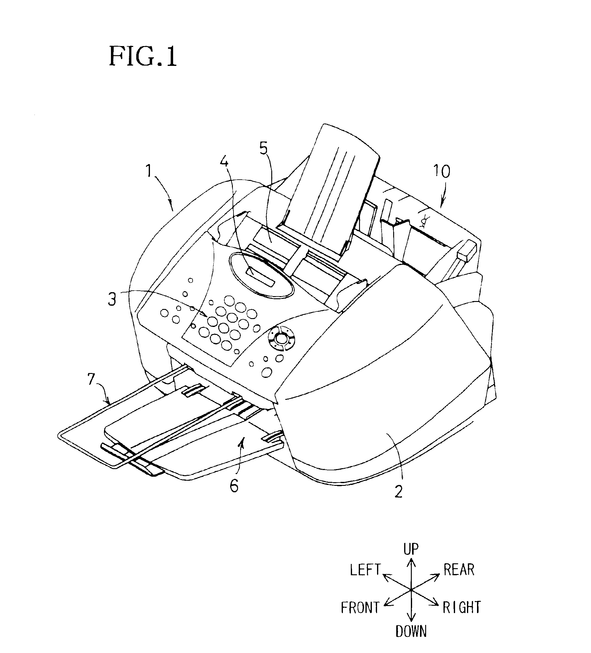
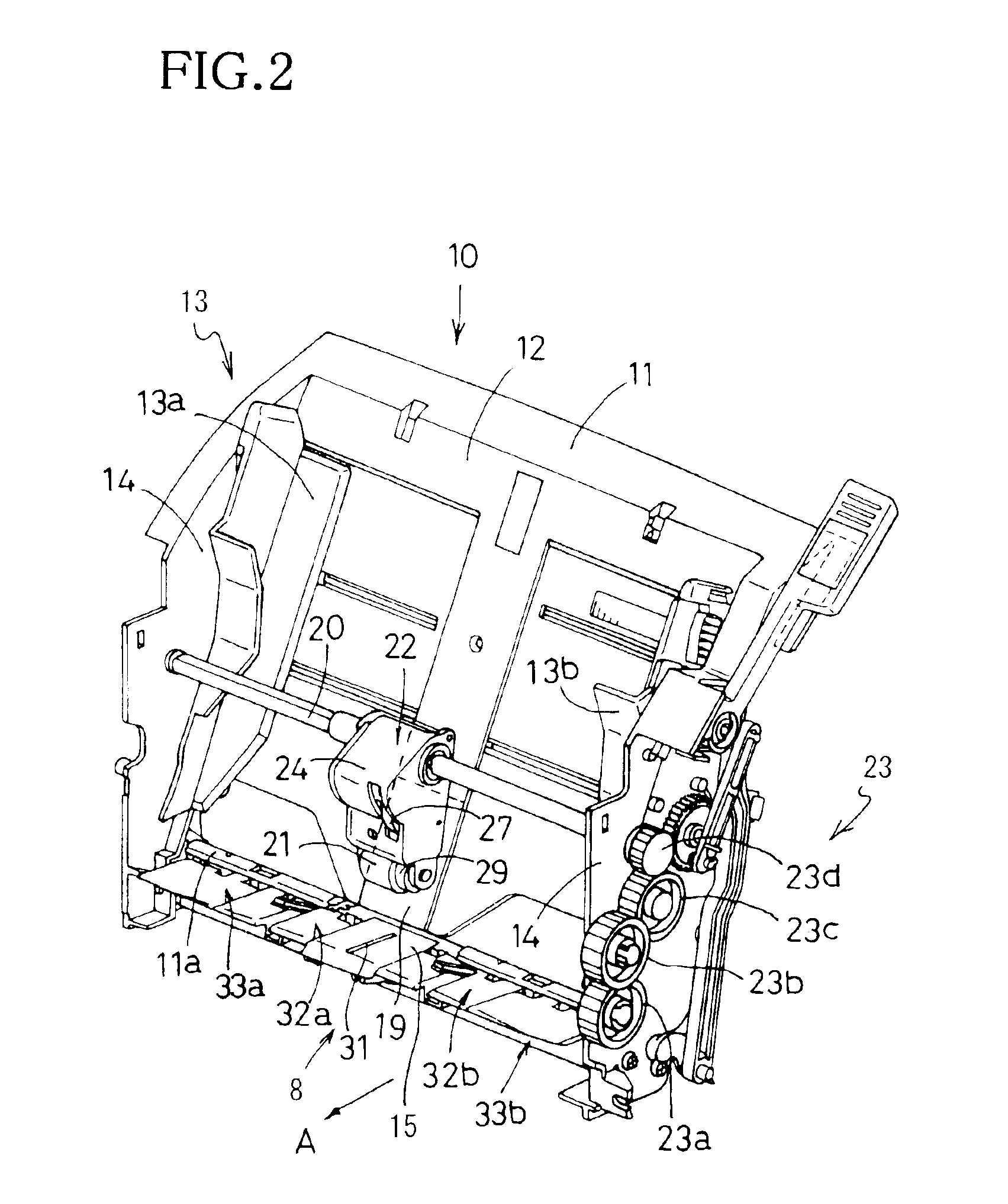
[0031]A multifunctional image forming apparatus 1 of FIG. 1 has a facsimile function, a printing function, a copying function, and a scanning function. As shown in FIG. 1, the image forming apparatus 1 includes a substantially box-shaped body 2. The body 2 has an operating panel 3 on its upper surface. The operating panel 3 is provided with various buttons and / or keys, such as a start button, numeric (0 to 9) buttons, and function keys. By pressing the buttons and keys, various operations are performed. A liquid crystal display (LCD) 4 is provided at an upper portion of the operating panel 3 to display setting conditions of the image forming apparatus 1 and various messages as needed. A side, on which the operating panel 3 is provided, is defined as a front of the image forming apparatus 1, and an opposite side is defined as a rear of the image form...

second embodiment

[0066]In the above-described embodiments, the description has been made by applying the invention to the multifunctional image forming apparatus 1. However, if an image forming apparatus includes the sheet feeder 10 of either of the above-described embodiments, the invention can be applied thereto. For example, the invention can be applied to a printer that does not have a facsimile function if the printer includes the sheet feeder 10 of either of the embodiments. According to the image forming apparatus including the sheet feeder 10 of either of the first or second embodiment, the multi-feed problem can be surely prevented. Therefore, predetermined images can be surely formed on sheets P, which are supplied one by one, by the image forming unit.

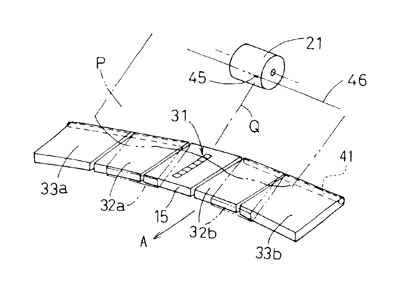
[0067]In the above-described embodiments, the sheets P are guided by the pair of the guide members 13a, 13b to contact the middle points of the leading edges of the sheets P with the sheet separating unit 31 (the separating strip 34), regard...


PUM


Abstract

An auxiliary support plate is connected, by a leaf spring, to a middle portion of a lower end of a sheet holder, in a sheet width direction, so that a lower end part of the auxiliary support plate rotates and retracts below an upper surface of the sheet holder. A sheet feed roller, facing an upper surface of the auxiliary support plate, is rotatably supported by an arm, which can rotate about a drive shaft disposed upstream in a sheet advance direction.

Description

BACKGROUND OF THE INVENTION[0001]1. Field of Invention[0002]The invention relates to a sheet feeder that feeds cut sheets and an image forming apparatus including the sheet feeder, and more particularly, to a device that separates and feeds sheets, one by one, by abutting leading edges of the sheets in a sheet feed direction against an inclined separating surface formed by separating plates.[0003]2. Description of Related Art[0004]Conventional image forming apparatuses, such as laser-beam printers, color ink-jet printers, facsimile machines and copying machines, include a sheet feeder that feeds cut sheets, one by one, to an image forming unit provided therein. As disclosed in U.S. Pat. No. 6,158,733 and Japanese Laid-Open Patent Publication No. 2001-278507, the sheet feeder includes an inclined sheet holder, which holds a stack of sheets thereon, a separating plate, which is disposed below the sheet holder and has an inclined separating surface, and a sheet feed roller that is atta...

Claims


Application Information

Patent Timeline
Patent Type & Authority Patents(United States)
IPC IPC(8): B65H3/34B65H3/52B41J13/00B65H1/12B65H3/06B65H3/56
CPCB65H3/0661B65H3/56B65H2405/1136B65H2405/11162
Inventor TAKITO, KOJIITO, SHINGO
Owner BROTHER KOGYO KK
Why Eureka
Try Eureka