Adjustable length suspension fork for a bicycle

a suspension fork and adjustable technology, applied in the direction of shock absorbers, steering devices, cycle equipments, etc., can solve the problems of unsatisfactory static friction, limited torsional stiffness of these types of assemblies, and suspension systems using such bushings tend to stick and release, so as to shorten the needed length of tubes, improve the strength characteristics of the suspension fork and improve the ride attitude

Inactive Publication Date: 2006-03-14
KINZLER FREDERICK W +1
View PDF7 Cites 44 Cited by
  • Summary
  • Abstract
  • Description
  • Claims
  • Application Information

AI Technical Summary

Problems solved by technology

These bushings, by themselves, have undesirable static friction called “stiction.” Because of this, the suspension systems using such bushings tend to stick and release.
Even with this “U” shaped yoke the torsional stiffness of these types of assemblies is still limited.
These forks are also heavy.
With the current needle bearing system, several problems exist to incorporate the torsional rigid features it provides with longer travel and suspension length adjustment.
High strength steel is commonly used for the inner tube for this purpose, but it is heavy and counter to the consumer's preference.
Here-to-for, unfortunately, telescope assemblies whose inner tube connects to the fork crown with greater than 70 mm length of travel have been unable to pass stress testing using the present art as described in the aforementioned patents despite the additional costly process of shot-peening and use of expensive high-strength aluminum alloys.
Attempting to increase the diameter of the tubes to add strength is also impractical as larger tube diameters increase cost, obsolete existing factory tooling and is generally counter to the consumer's aesthetic preference.
The main drawback of these systems is their limitation on the length of travel of the suspension system.
Trying to increase this length to 100 mm poses significant problems.
The length of a 100 mm telescoping suspension portion of the fork using this approach would be in excess of 9 inches putting the attitude of the bike at a steep undesirable angle.
Even then the stress on the inner tube member would be so great as to fail during use.
While these systems work they are costly and heavy.
Such a restriction adds to the overall length of the telescoping system as the size of the damper components are greater than the space available in the inner tube.
Unfortunately, the race stock is heavy steel and as the suspension system length grows, the length of the race stock grows increasing the weight of the system.
If the bearing needles escape, the entire front fork may come apart.
Because of the flexing, however, it cannot be closed down enough to encounter the full length of the bearing cage because the bending of the inner tube when under load may cause it to rub against the collar.
As the length of travel is increased this compromise becomes more difficult to make.
Currently no adjustable mechanism exists for Ferris et al. designed suspension forks with the ability to change suspension length at the handlebars.
Damper systems of most suspension forks other than those incorporating the single tube suspension unit described by Farris et al. are adjustable at the top of the crown or at the bottom of the suspension fork which is inconvenient for the user to make adjustments.
In addition, many damper systems do not progressively stiffen as the length of travel is used causing topout of the damper and unnecessary roughness.
These devices are not infinitely adjustable between two fixed travel positions therefore they do not allow the rider to adjust to a convenient position.

Method used


Image

  • Adjustable length suspension fork for a bicycle
  • Adjustable length suspension fork for a bicycle
  • Adjustable length suspension fork for a bicycle

Examples


Embodiment Construction

Telescoping Housing Mechanism

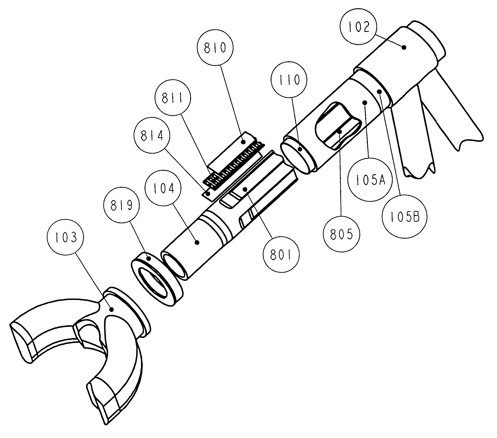
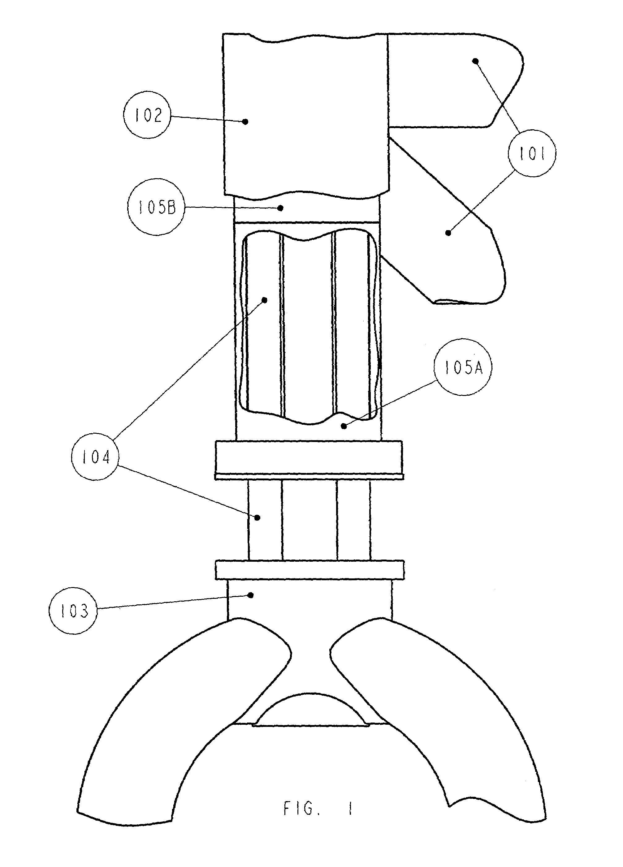
[0039]FIG. 1 shows a bicycle frame (partial) 101 along with a head tube 102. A fork crown (partial) 103 has an inner tube 104 of a telescoping assembly affixed into it. The outer tube, comprised of two pieces 105A and 105B of the telescoping assembly is pressed into the head tube 102 using upper and lower journal bearings (not shown) to allow for steering rotation. The upper end of the outer tube 105B is connected to the handlebar stem (not shown). It should be noted that for this embodiment the outer tube is comprised of two pieces, however, the outer tube could be one piece.

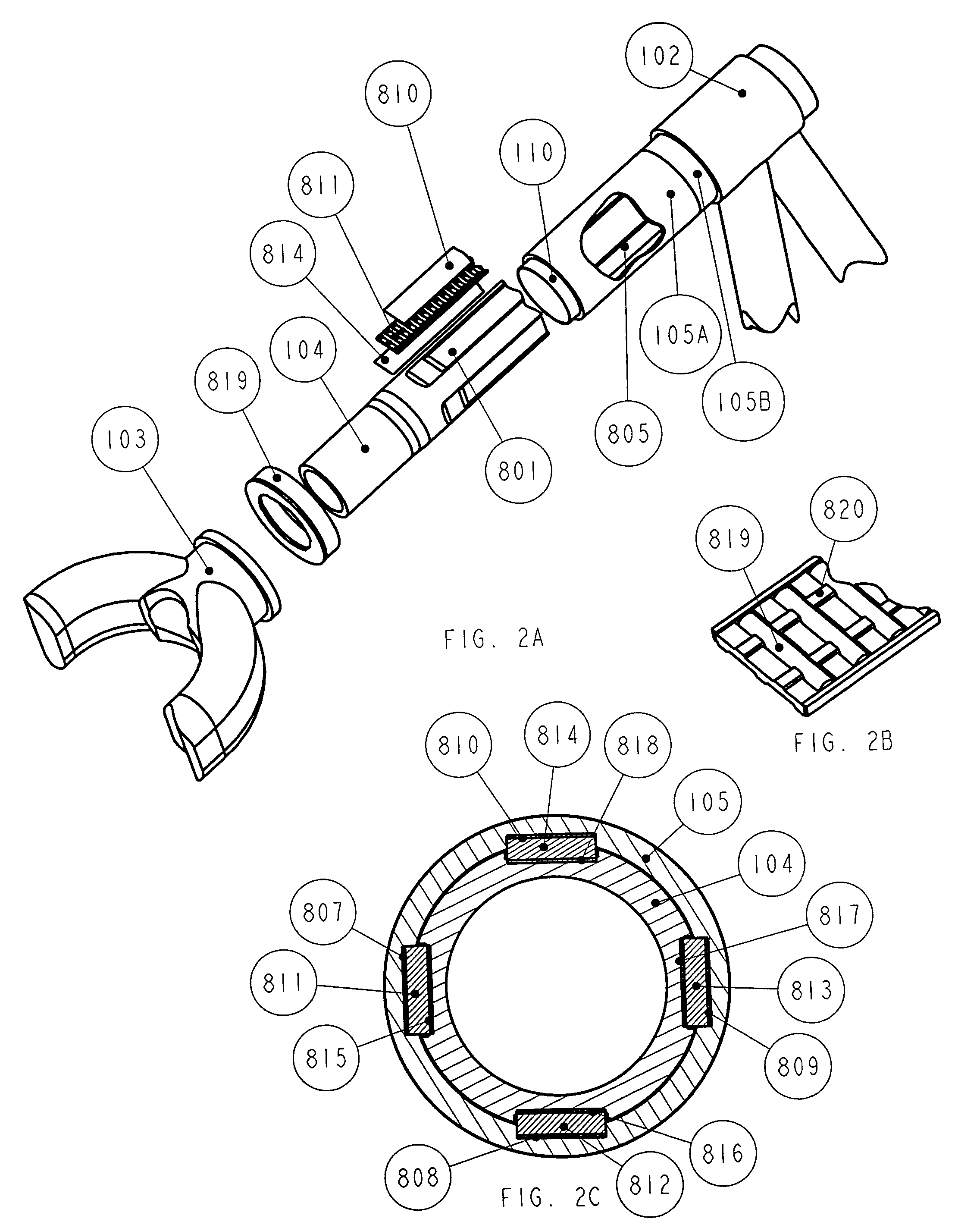
[0040]FIG. 2A is an exploded view of the telescoping assembly showing parts germane to this invention. Over a specific length in the outer wall of the inner tube 104 depicts a plurality of axially extending longitudinal flat surfaces or flats of which one is shown 801. In the preferred embodiment there are four such flats, however there can be more or less flats used. Over a specifi...


PUM


Abstract

An improved, lightweight suspension fork for a bicycle with variable travel capability that maintains excellent torsional rigidity. This suspension fork allows for adjustable suspension travel adjusted at the handlebars of the bicycle. The suspension system includes a travel adjustment knob located at the handlebars of the bicycle. The travel adjustment knob is keyed with the main shaft of the suspension system so as to allow turning of the main shaft. Located on the main shaft within the suspension system housing is a length adjuster mechanism. The length adjuster moves linearly with respect to the housing as the main shaft is turned pulling the inner tube member of the suspension housing up or down relative to the outer tube section of the suspension housing, thereby changing the stroke of the suspension system.

Description

CROSS-REFERENCE TO RELATED APPLICATIONS[0001]This application claims the benefit of provisional patent application 60 / 470,726 filed May 15, 2003 by the present inventors.RELATED U.S. APPLICATION DATA[0002]U.S. CL . . . 280 / 276; 74 / 492; 188 / 271; 267 / 216; 280 / 283; 280 / 284; 280 / 777 188 / 319.1, 188 / 285[0003]Int. Cl . . . B62K 025 / 08[0004]Field of Search . . . 188 / 281; 188 / 266.4; 188 / 312; 188 / 315; 188 / 322.11; 188 / 313; 188 / 318; 188 / 319.1; 188 / 313; 188 / 317; 188 / 285; 280 / 276; 280 / 279; 280 / 284; 280 / 5.513; 280 / 5.501; 280 / 5.508; 280 / 5.514[0005]References Cited:[0006]U.S. PATENT DOCUMENTS6,533,459March 2003Podhajecki et al.384 / 576,382,370May 2002Girvin188 / 299.16,360,857March 2002Fox188 / 2816,328,291December 2001Marzocchi et al.267 / 64.56,305,704October 2001Vignocchi et al.280 / 2796,505,719January 2003Gonzalez et al.188 / 319.26,360,858March 2002Gonzalez et al.188 / 319.26,241,060June 2001Gonzalez et al.188 / 319.25,380,026January 1995Robinson280 / 2766,145,862November 2000D'Aluisio et al.280 / 2766,135,477Oc...

Claims


Application Information

Patent Timeline
Patent Type & Authority Patents(United States)
IPC IPC(8): B62K25/10B62K21/20B62K21/22
CPCB62K21/22B62K21/20
Inventor KINZLER, FREDERICK W.WOODWORTH, WALKER P.
Owner KINZLER FREDERICK W
Why Eureka
Try Eureka