Surgical suturing instrument and method of use

a suturing instrument and suturing technology, applied in the field of surgical suturing instruments and methods, can solve the problems of insufficient flexibility of devices with regard to suturing, large hole in the subject of the needle, and inability to adjust the suturing angl

Inactive Publication Date: 2006-03-14
DVL ACQUISITION SUB
View PDF273 Cites 46 Cited by
  • Summary
  • Abstract
  • Description
  • Claims
  • Application Information

AI Technical Summary

Benefits of technology

[0018]And in a further feature of the invention, a cutting mechanism is provided to permit the flexible elongated element to be cut with varying lengths. As a result, the flexible elongated element

Problems solved by technology

This has the disadvantage that the needle typically leaves a larger hole in the subject than is necessary to accommodate only the suture material itself.
However, this device does not permit adequate flexibility with regard to the amount of tension that may be applied to the suture and tissue.
Unfortunately, however, such a system does not permit much flexibility when it comes to the amount of tension to be applied to the subject, since the wire is relatively firm (i.e., firm enough to hold its sets).
Such a system also does not provide any flexibility with respect to the type of suture stitch to be applied, since the device is specifically configured to provide only a spiral suture s

Method used


Image

  • Surgical suturing instrument and method of use
  • Surgical suturing instrument and method of use
  • Surgical suturing instrument and method of use

Examples


Embodiment Construction

Overview

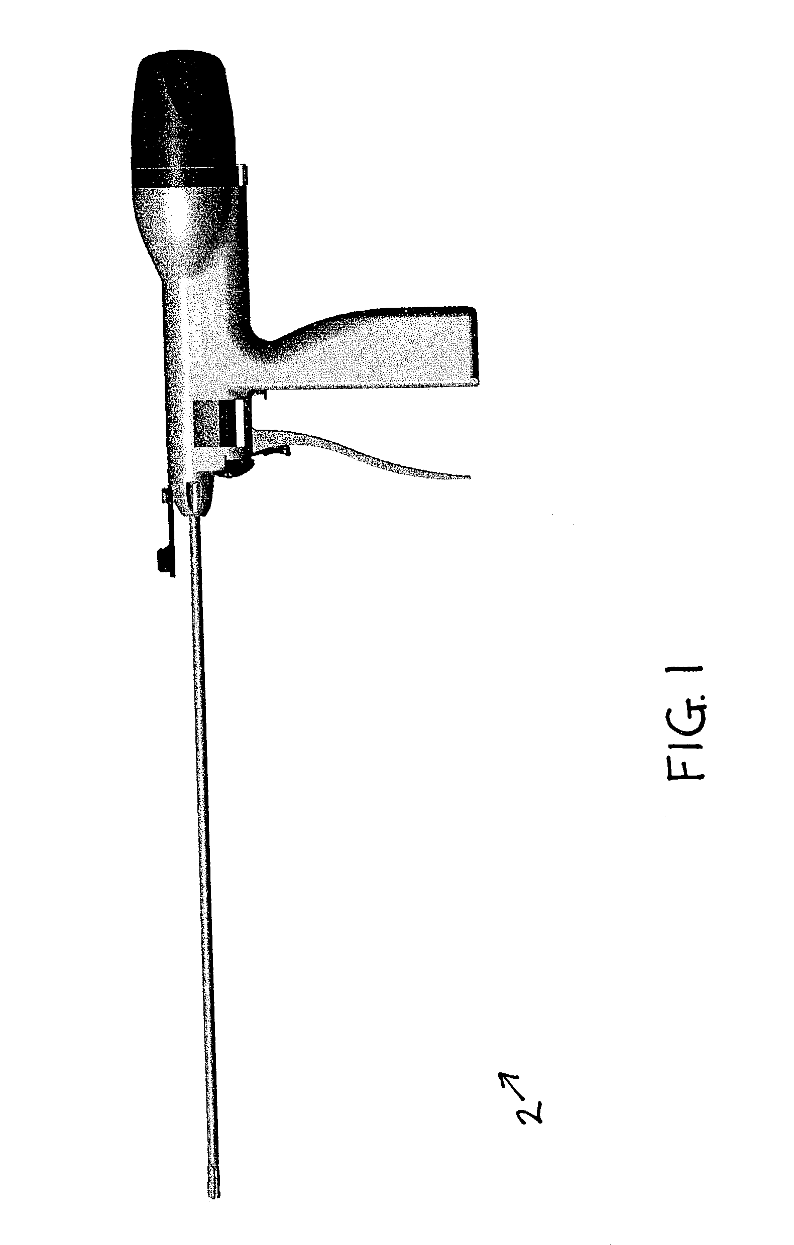
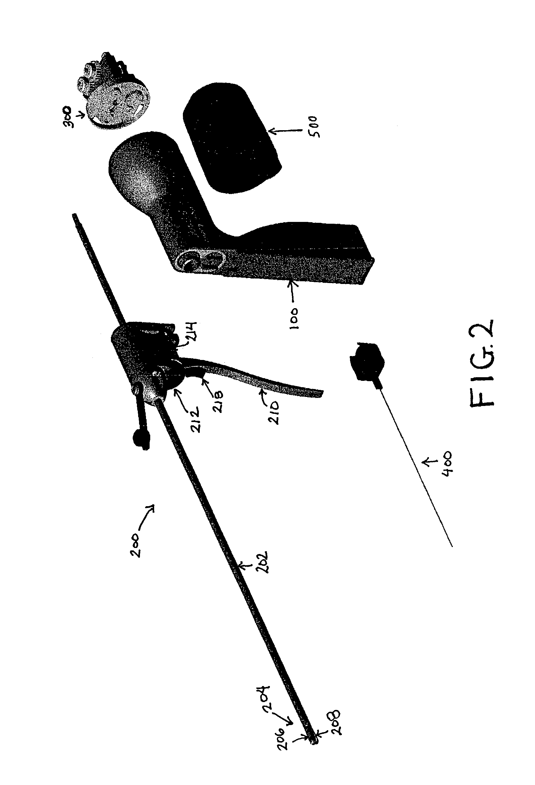
[0033]Looking first at FIGS. 1–3, there is shown a suturing instrument 2 which comprises a preferred embodiment of the present invention. Suturing instrument 2 generally comprises a handle assembly 100, a cannula assembly 200, a wire drive assembly 300, a wire supply cartridge 400 and a shroud assembly 500, as will hereinafter be described in further detail.

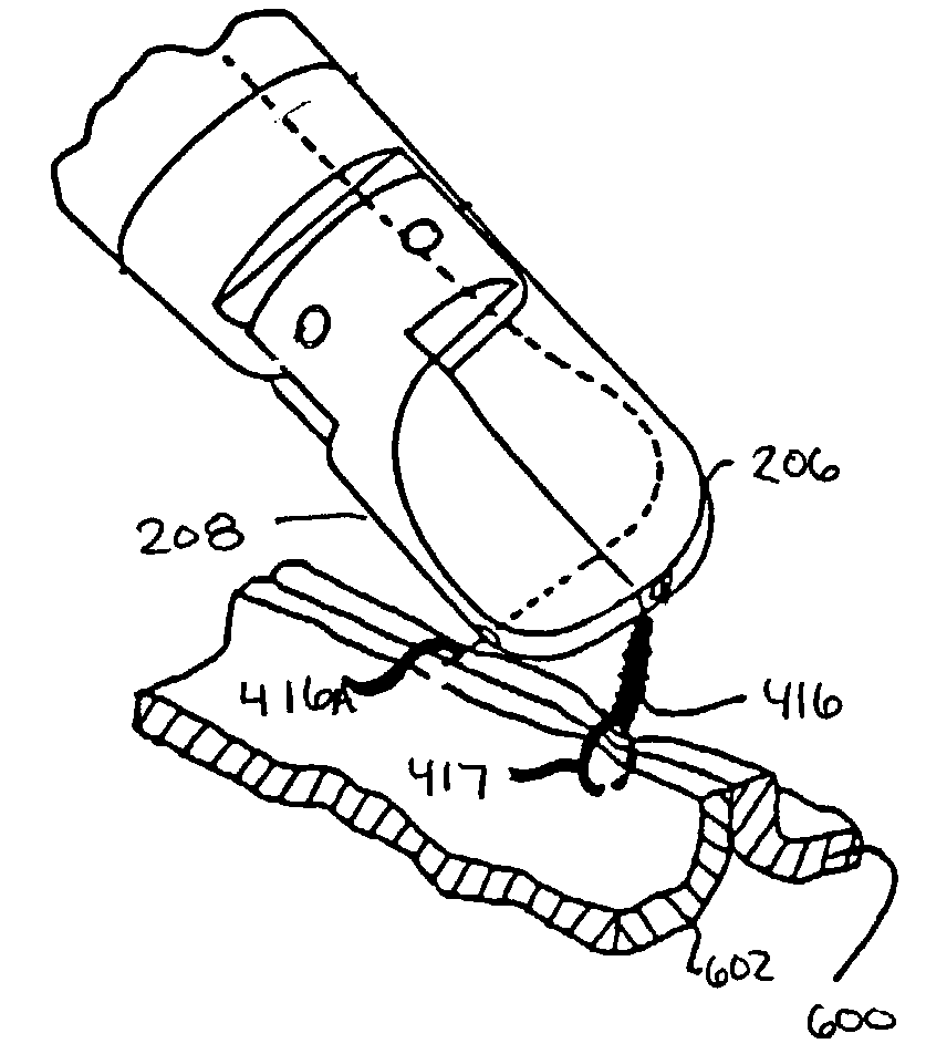
[0034]Among other things, cannula assembly 200 comprises a shaft 202, an end effector 204 comprising a first jaw 206 and a second jaw 208, a jaw closing actuator 210, a wire advance button 212, a left rotation button 214, a right rotation button 216 (FIG. 3), and a wire cutting actuator 218, as will also hereinafter be described in further detail.

[0035]As will be discussed in further detail below, generally during use, the suturing instrument's end effector 204 is positioned adjacent to the tissue which is to be sutured and, using jaw closing actuator 210, jaws 206 and 208 are brought together around the tissue which is t...


PUM


Abstract

A device is disclosed for introducing a flexible elongated element through at least two portions of a subject. In an embodiment, the device includes a proximal end and a distal end, as well as an advancement unit for longitudinally advancing the flexible elongated element toward the distal end such that a proximal end of the elongated element may pass from the distal end of said device with sufficient force to pass through the portions of the subject. The device also includes a securing unit for variably adjusting a securing force applied by the flexible elongated element to secure together the portions of the subject.

Description

REFERENCE TO EARLIER APPLICATIONS[0001]This is a continuation-in-part of pending prior U.S. patent application Ser. No. 10 / 014,991, filed Dec. 11, 2001 by Gregory E. Sancoff et al. for SURGICAL SUTURING INSTRUMENT AND METHOD OF USE.[0002]This patent application also claims benefit of pending prior U.S. Provisional Patent Application Ser. No. 60 / 307,255, filed Jul. 23, 2001 by Gregory E. Sancoff et al. for SURGICAL SUTURING INSTRUMENT AND METHOD OF USE.[0003]The two above-identified patent applications are hereby incorporated herein by reference.FIELD OF THE INVENTION[0004]This invention relates to medical instruments and procedures in general, and more particularly to suturing instruments and methods for suturing.BACKGROUND OF THE INVENTION[0005]Suturing instruments are typically used to draw together two or more portions of a subject patient (e.g., tissue such as muscle or skin) or to attach an object to the patient (e.g., to attach a piece of surgical mesh to the abdominal wall of...

Claims


Application Information

Patent Timeline
IPC IPC(8): A61B17/04A61B17/00A61B17/064A61B17/068
CPCA61B17/064A61B17/068A61B2017/0646A61B2017/00004
Inventor SANCOFF, GREGORY E.FOGG, DOUGLAS A.FIELD, FREDERIC P.
Owner DVL ACQUISITION SUB
Why Eureka
Try Eureka