

Bidet
a technology of abidet and a sleeve is applied in the field ofbidets, which can solve the problem that the pressure of the supply line may exceed the safe limit, and achieve the effect of preventing water backflow
- Summary
- Abstract
- Description
- Claims
- Application Information
AI Technical Summary
Benefits of technology
Problems solved by technology
Method used
Image

Examples
Embodiment Construction
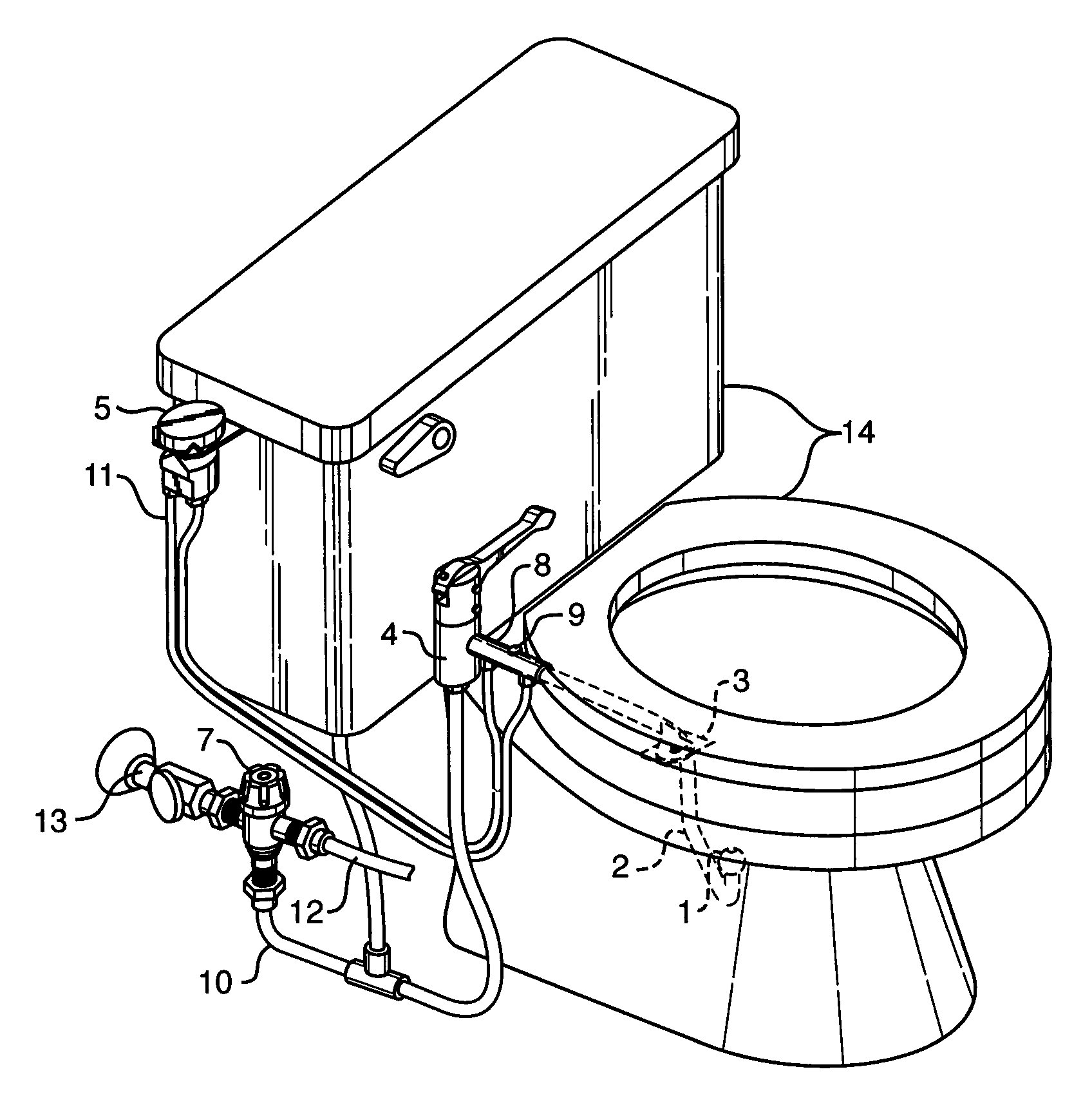
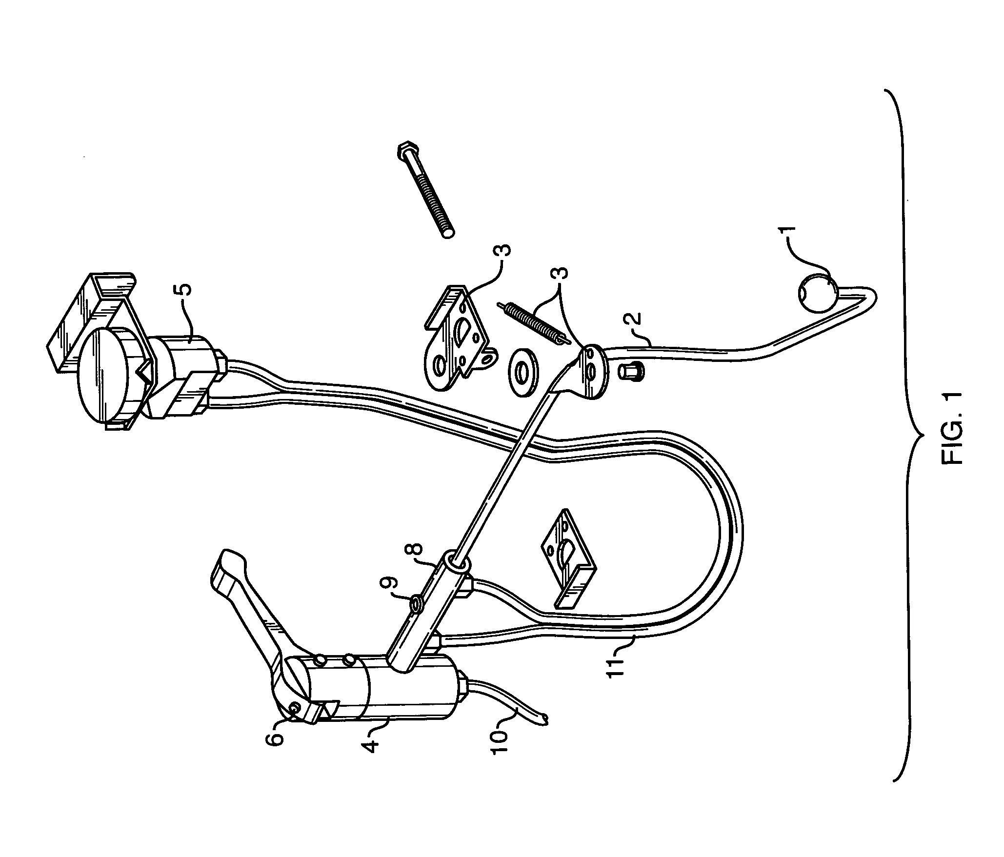
[0009]Turning first to FIG. 1 there is shown the present invention, Bidet, in a partially assembled configuration. Shown are removable spray nozzle 1, that is removably mounted on a tubular spray arm 2. The spray nozzle could have male threads at the tubular spray arm end with female threads on the tubular spray arm, or the spray nozzle could be frictionally secured to the tubular spray arm. There are other methods of attachment that could be used that would permit secure, but not permanent, attachment and at the same time ease of removal. The tubular spray arm is formed of a tubular member 2, having a first end 19, a second end 20, and a mid section 21. Said tubular member is shaped to accommodate the curvature of a toilet bowl and seat. In the preferred embodiment the spray nozzle is sized and shaped to be frictionally secured onto the tubular member first end. The tubular spray arm 2 has a spring activated bracket 3, shown in a disassembled configuration. The spring activated bra...
PUM
 Abstract
Description
Claims
Application Information