
Bidet

a technology of abidet and a sleeve is applied in the field ofbidets, which can solve the problem that the pressure of the supply line may exceed the safe limit, and achieve the effect of preventing water backflow

Inactive Publication Date: 2005-04-28
PACHECO MANUEL A
View PDF5 Cites 12 Cited by
  • Summary
  • Abstract
  • Description
  • Claims
  • Application Information

AI Technical Summary

Benefits of technology

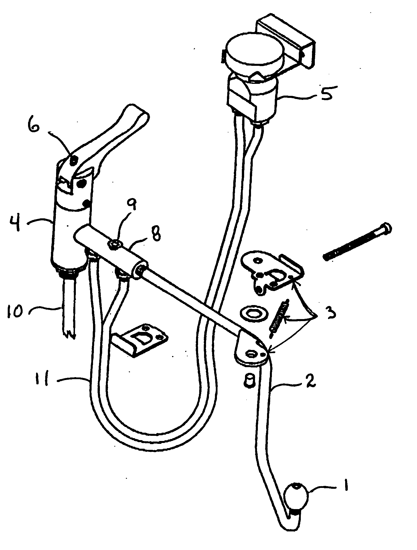
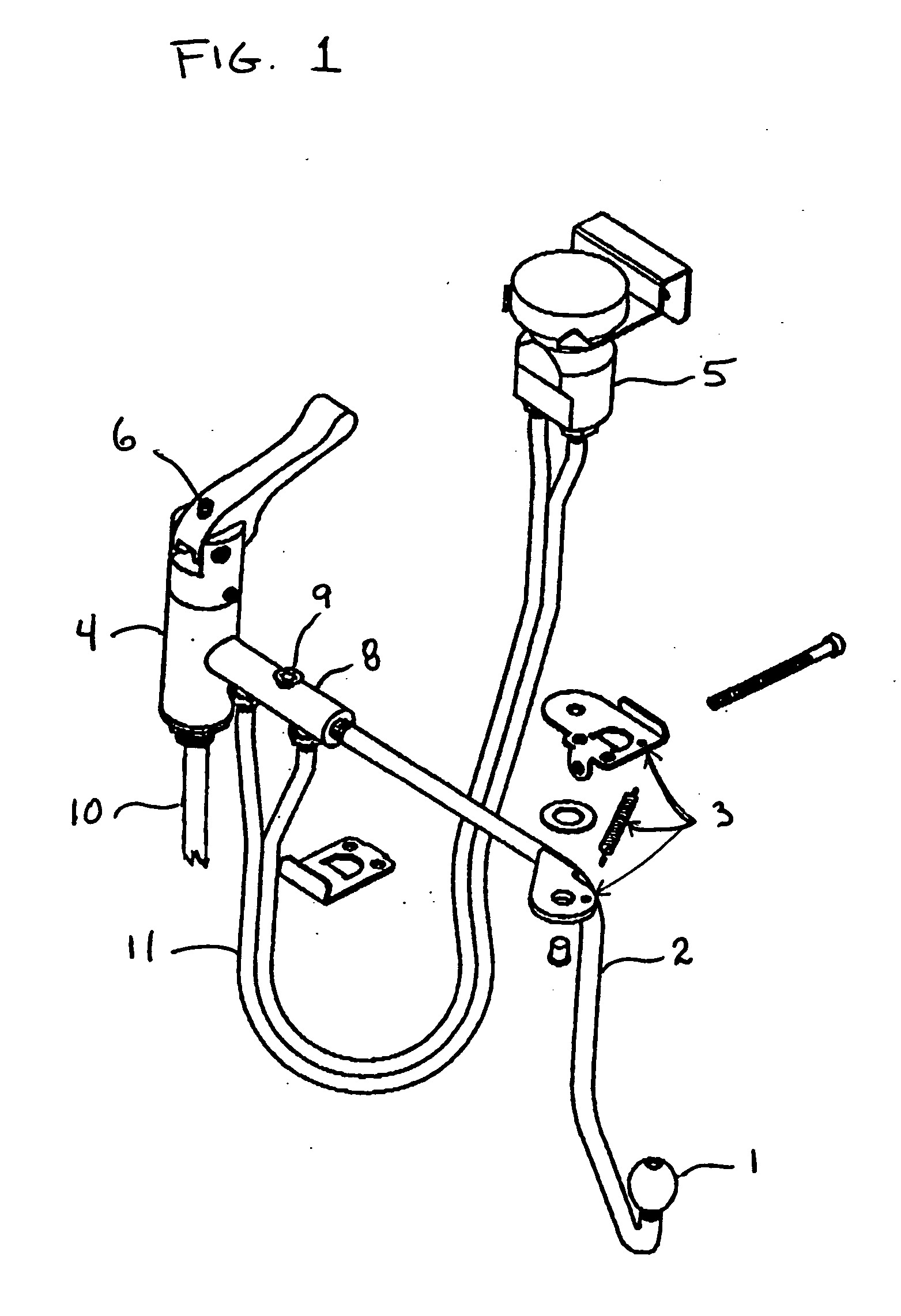
[0009] Turning first to FIG. 1 there is shown the present invention, Improved Bidet, in a partially assembled configuration. Shown are removable spray nozzle 1, that is removably mounted on a tubular spray arm 2. The spray nozzle could have male threads at the tubular spray arm end with female threads on the tubular spray arm, or the spray nozzle could be frictionally secured to the tubular spray arm. There are other methods of attachment that could be used that would permit secure, but not permanent, attachment and at the same time ease of removal. The tubular spray arm 2 has a spring activated bracket 3, shown in a disassembled configuration. The spring activated bracket 3 is comprised of a mounting plate, that would be used to secure the bracket to the underside of a conventional toilet seat, a washer, a pin, a spray arm plate fixedly secured to the spray arm and a spring. The pin is situated in order that the pin goes thru a hole in the mounting plate and a hole in the spray arm plate forming an axis of rotation for the spray arm plate. The spring activated bracket 3 would be mounted to the underside of a conventional toilet seat portion of a conventional toilet bowl that are not shown. The mounting to the underside of the conventional toilet seat could make use of a bolt or pin for quick removal. The spring portion of the spring activated bracket 3 extends as the tubular spray arm 2 is moved to place the spray nozzle 1 in the area of intended use, causing tension on the spring, and returns the tubular spray arm 2 to an out of the way position under the seat or against the side of the toilet bowl when the tubular spray arm is released and not in use. The removable spray nozzle I allows for cleaning and sanitation of the removable spray nozzle 1 without any time consuming or complicated procedure. As the removable spray nozzle 1 is easily removable it is also possible to have several spray nozzles with different spray patterns to accommodate the users individual preference. It also allows for unique requirements due to the individual's personal physical or medical requirements.
[0010] The pivotal mounting of the tubular spray arm 2, at the spring activated bracket 3, allows for individual needs or preferences of the user as to spray location. With a spring activated bracket 3 the tubular spray arm 2 and removable spray nozzle 1 are quickly and safely removed from the spray area when not in use. The first end of the spring is attached to the portion of the spring activated bracket that is secured to the underside of the toilet seat with the second end of the spring being attached to the portion of the spring activated bracket that is fixedly secured to the tubular spray arm. The spring is sized and shaped in order that the spring tension causes the tubular spray arm to remain in an inactive position unless pressure is applied to the tubular spray arm causing the tubular spray arm to swing into the active position. The tension of the spring when in the active position is such that the user is not required to apply an inordinate amount of force.
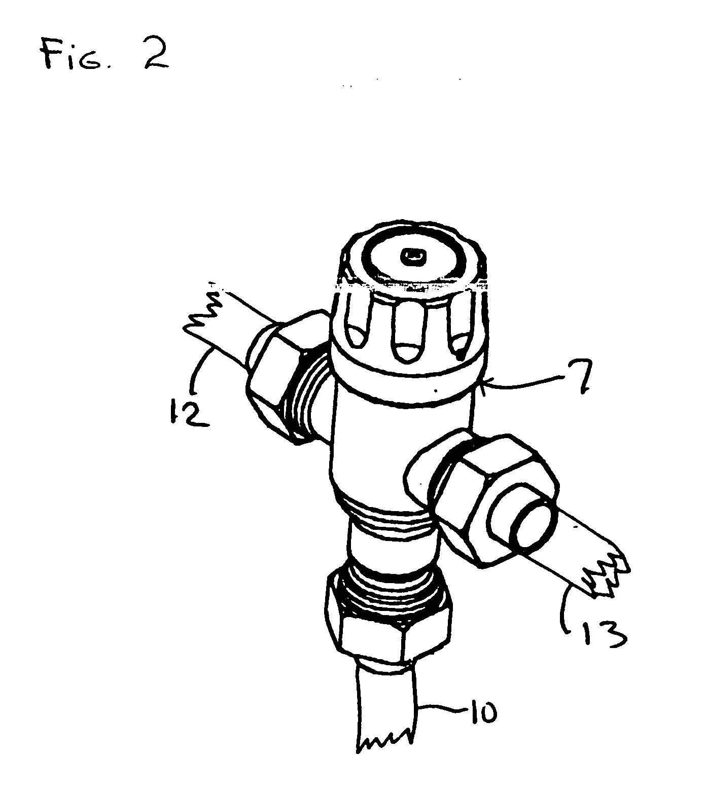
[0013] Water temperature is also of major importance to insure that the users skin is not exposed to water that exceeds safe limits. The present invention provides a mixing valve 7, shown in FIG. 2, that combines the input hot water with the input cold water. The mixing valve 7 is designed to restrict the combined water temperature to be no more than 110° F. This reduces the possibility of injury due to fluctuating temperature of the input hot water. The mixing valve has an adjustment knob that permits the varying of the ratio of hot water to cold water from a ratio were no hot water is entering the valve with the resultant combined outlet water being the temperature of the cold water to a ratio were sufficient hot water is entering the valve with the resultant combined outlet water being no more than 110° F. The mixing valve would be a standard off the shelf item.
[0015] Also incorporated is a diverter T 8 that permits the addition of various substances at an injection port 9 into the spray water. The substances would usually be in liquid form however it would be possible to add dissolvable crystals, cubes or gels. The substance being added could be scented, anti bacterial, medicated or a cleansing agent. The diverter T 8 also prevents water backflow. Conventional supply lines provide hot and cold water to the mixing valve 7 which then supplies the combined hot and cold water to the bidet. A double hose service hose 11 is used to pass the water thru the vacuum breaker 5 and also the diverter T 8.
[0017] As shown several of the components may be connected by the use of threaded joints, including the tubular spray arm and spray nozzle for increased ease in removal and replacement.

Problems solved by technology

In some installations the supply line pressure may exceed safe limits for direct skin contact, or may fluctuate and from time to time exceed the safe limit.

Method used


Image

  • Bidet
  • Bidet
  • Bidet

Examples


Embodiment Construction

[0009] Turning first to FIG. 1 there is shown the present invention, Improved Bidet, in a partially assembled configuration. Shown are removable spray nozzle 1, that is removably mounted on a tubular spray arm 2. The spray nozzle could have male threads at the tubular spray arm end with female threads on the tubular spray arm, or the spray nozzle could be frictionally secured to the tubular spray arm. There are other methods of attachment that could be used that would permit secure, but not permanent, attachment and at the same time ease of removal. The tubular spray arm 2 has a spring activated bracket 3, shown in a disassembled configuration. The spring activated bracket 3 is comprised of a mounting plate, that would be used to secure the bracket to the underside of a conventional toilet seat, a washer, a pin, a spray arm plate fixedly secured to the spray arm and a spring. The pin is situated in order that the pin goes thru a hole in the mounting plate and a hole in the spray arm...


PUM


Abstract

This is a Bidet with a variable position removable spray nozzle, a spring activated means to withdraw the spray nozzle from the normal area of use when not in use, a means to provide variable pressure of spray, a means for mixing input hot water with input cold water to allow for adjustable water temperature within a controlled range, a means for adjusting the water pressure and volume within a controlled range, a vacuum breaker to prevent water backflow, and a diverter T for selectively adding substances that are either scented, anti bacterial, medicated or cleansing agent to spray, and in addition preventing water backflow.

Description

BACKGROUND [0001] The field of my invention is Bidets of the type typically found in home bathrooms. The invention portrayed is an improved Bidet. There are many Bidets that have been manufactured over the years, from the simple hand held spray wand to the more elaborate. The present invention is an improved Bidet that overcomes several problems. My invention permits the Bidet to be used in conjunction with a toilet as found in most household bathrooms. In some Bidets that are on the market the spray comes from a nozzle that can be operated from only one fixed position. This may be acceptable for most applications however, many users have peculiar situations requiring aiming the nozzle and therefore the spray at a specific area or areas. Several Bidets have spray nozzles that cannot be easily removed for cleaning or replacement. The present invention incorporates a variable position arm with removable spray nozzle. The variable position arm may be attached, to the toilet bowl with a...

Claims


Application Information

Patent Timeline
IPC IPC(8): E03D9/08
CPCE03D9/08
Inventor PACHECO, MANUEL A.
Owner PACHECO MANUEL A
Learn More