
Interchangeable needle safety syringe

Inactive Publication Date: 2006-03-21
RETRACTABLE TECH INC
View PDF19 Cites 45 Cited by
  • Summary
  • Abstract
  • Description
  • Claims
  • Application Information

AI Technical Summary

Benefits of technology

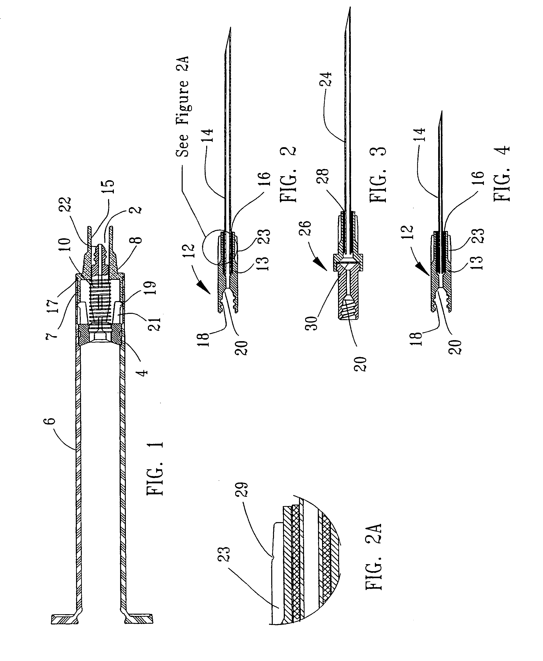
[0007]Continued force causes the head of the needle hub to tear the web of the boot, positioning the needle hub just inside a hollow portion of the plunger. The torn portion of the web creates a flap just inside the hollow plunger. As the plunger moves the deformable base still further, the needle hub eventually looses contact with the deformable base, which triggers a release of energy from the energy storage means in the passageway, projecting the needle hub with its changeable needle attached thereto into the hollow portion of the plunger. Once inside the plunger, the needle hub is trapped by its enlarged head behind a flexible catch within the plunger. Final movement of the plunger causes the plunger to become substantially locked in the barrel and causes a liquid tight seal to be created between the plunger and the syringe body. A closing member placed on the front of the needle assembly completely seals the syringe to prevent residual fluids from escaping. Completion of the needle retraction also automatically highlights an indicia such as a biohazard label which alerts persons handling the device that the syringe has been used and represents a potential biohazard.
[0016]to provide a simple device, which is manufacturable in high volumes.

Problems solved by technology

In other words, one cannot require substantial force for detachably inserting and removing the different sizes and types of needles because otherwise the act of interchanging needles will cause the syringe to trigger, this rendering it useless.

Method used


Image

  • Interchangeable needle safety syringe
  • Interchangeable needle safety syringe
  • Interchangeable needle safety syringe

Examples


Embodiment Construction

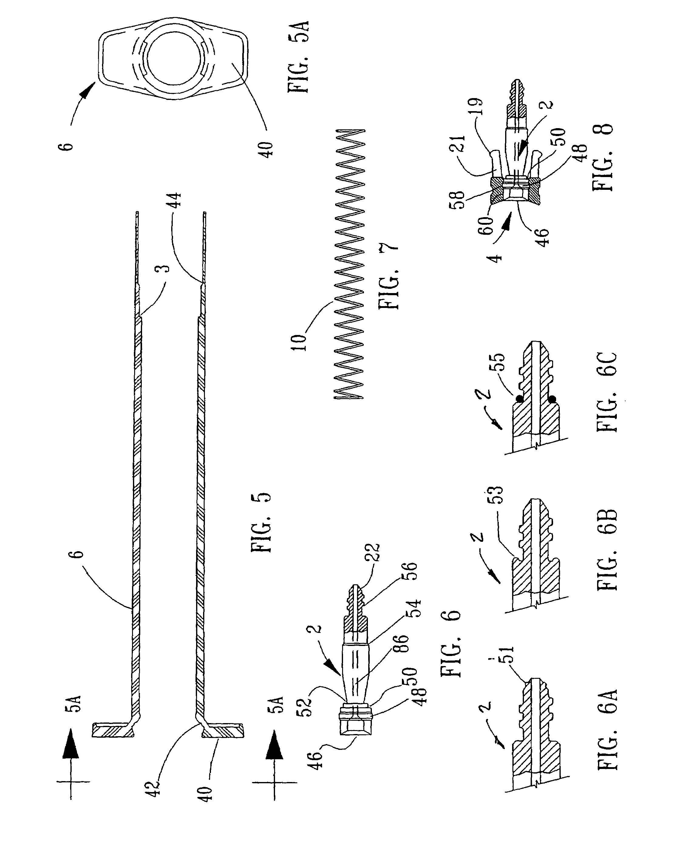
[0045]Before describing the drawings and embodiments in more detail, several terms are described below in an effort to clarify the terminology used in this document. Additional and fuller understanding of these terms will be clear to persons skilled in this art upon reading this entire document:[0046]“Needle assembly”: refers to the area on the end of the syringe in which the needle, spring or base are assembled. The needle assembly can be a separate, physical piece that is attached to or associated with the rest of the syringe body. Alternatively, the needle assembly could be just the section of the syringe body near which the needle, spring, or base are partially or completely located.[0047]“Needle head”: refers to the end of the needle that is associated with the syringe and which has an enlarged area. The enlarged area may be formed as part of the needle itself, or may be an additional piece fitted to the needle end. The enlarged area may be formed of plastics, metal or other su...


PUM


Abstract

The present invention is a safety syringe for use with a plurality of interchangeable needles. The plurality of needles may be inserted by the user into the safety syringe for use. In operations, the user selects the desired needle, e.g., a needle having a particular gauge or size or of a particular type. The user inserts the needle into a safety syringe comprising a barrel, a needle assembly area located within or attached to the barrel and a plunger. The needle couples to the syringe by a number of means. For instance, a locking mechanism may be used by which a needle hub located within the needle assembly has an area adapted to mate with a corresponding area on the needle. Or, the needle may be formed as part of a separate needle assembly, whereby the user will place the entire needle assembly onto the end of the syringe barrel. During use, the user operates the syringe, using one hand to depress the plunger, which ultimately causes a spring to propel the needle into the barrel of the syringe.

Description

RELATED APPLICATIONS[0001]This application claims priority under U.S. law to U.S. Patent Application No. 60 / 120,622 filed Feb. 18, 1999, entitled “Interchangeable Needle Safety Syringe,” which is incorporated by reference herein.FIELD OF THE INVENTION[0002]This invention relates generally to the art of safety syringes and more particularly to a safety syringe with an interchangeable needle which reduces the likelihood of unintentional puncture or pricking of human skin.BACKGROUND OF THE INVENTION[0003]In recent history, the transmission of contagious diseases, particularly those brought about exclusively by the co-mingling of human body fluids, has been of great technological interest. One of the particular problems has been associated with the use and disposal of hypodermic syringes, particularly among healthcare professionals. There have been various devices developed for the destruction of the needles or cannula used in such syringes. Additional devices have been developed for ca...

Claims


Application Information

Patent Timeline
IPC IPC(8): A61M5/00
CPCA61M5/3234A61M5/3202A61M5/502A61M2205/583A61M2005/3101A61M2005/3106A61M5/508
Inventor PRESSLY, SR., WILLIAM B. S.BROCKWAY, SAMUEL G.VAUGHN, SR., CHARLES A.ELLIS, THOMAS R.
Owner RETRACTABLE TECH INC
Learn More