
Relaxed tolerance optical interconnect system capable of providing an array of sub-images

Inactive Publication Date: 2006-03-21
WAVEFRONT RES
View PDF11 Cites 27 Cited by
  • Summary
  • Abstract
  • Description
  • Claims
  • Application Information

AI Technical Summary

Benefits of technology

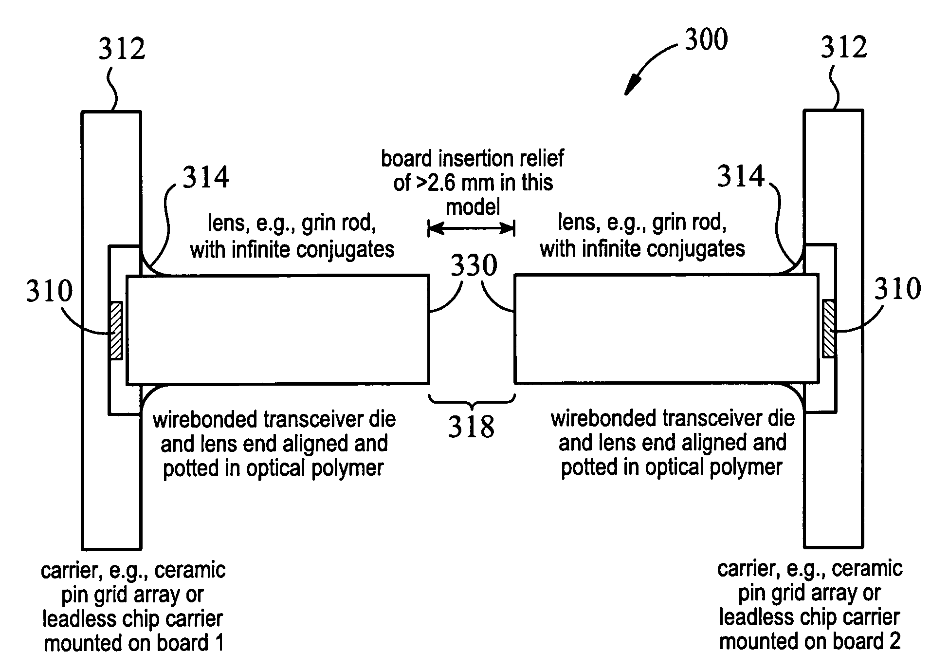
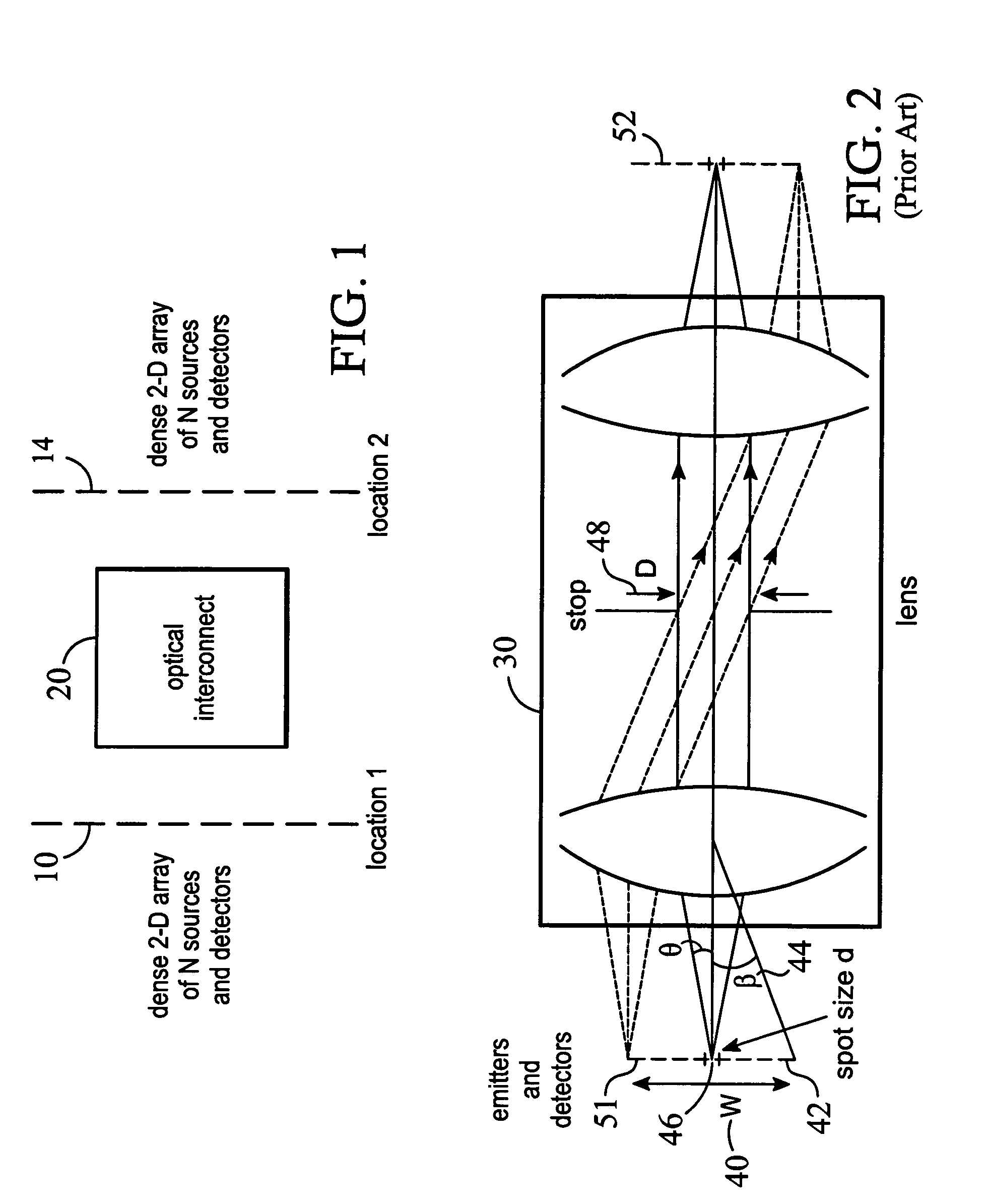
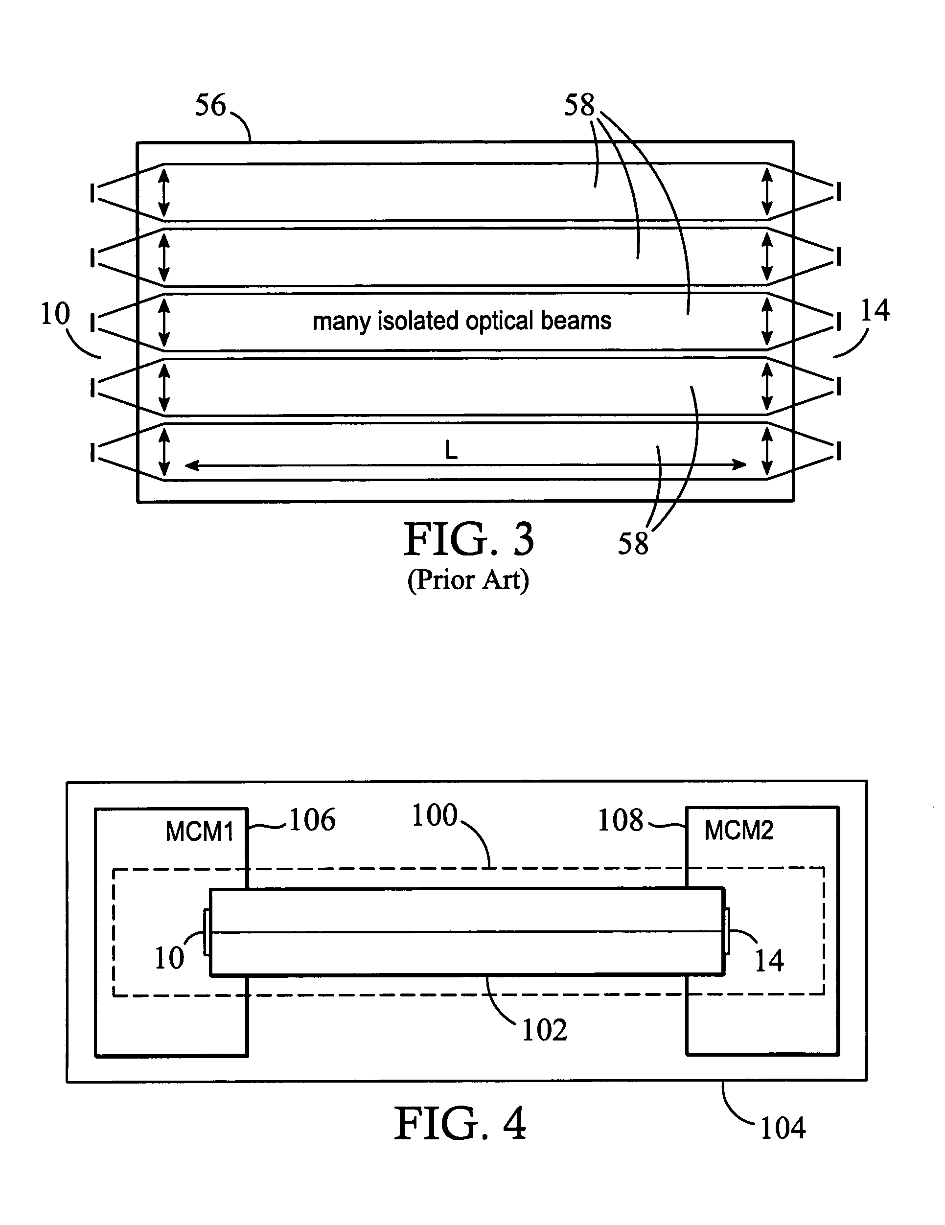
[0021]The present invention overcomes problems associated with size, power, crosstalk, and speed associated with conventional electrical interconnects, and overcomes problems with alignment tolerance in conventional optical interconnection. In a preferred embodiment of The optical interconnect system or optical data pipe approach of the present invention, although not limited thereto, mating emitter and detector arrays are pre-aligned and fixed on or near the ends of a gradient index rod imager, and this flexible pre-aligned structure is then mounted to the host. Using this technology, which includes the various embodiments of this invention, hundreds or thousands of high bandwidth channels can be interconnected for short distances (intra-die, between neighboring chips or MCMS) or over relatively long distances (full board wrap-around, board-to-board, computer to peripheral, computer to computer, etc.). The optical interconnect system of this invention provides a nearly lossless one-to-one optical interconnection from a set of input channels to a set of output channels, and supports extreme density, low power, and low crosstalk for high bandwidth signals.
[0022]One of many advantages of the system of this invention is that it can be pre-aligned and fixed during manufacture (e.g., using automated alignment and cementing procedures) to produce optical interconnects that have greatly relaxed alignment tolerances and are thus readily usable in the field by non-optical personnel. The interconnection systems of the present invention are thus tolerant of handling, bending and displacements among interconnected components without losing their function of interconnecting many closely packed (dense) optical channels. Other advantages of this invention relate to the fact that it is tolerant of misalignments, vibrations, etc.

Problems solved by technology

Conventional electrical interconnection over wires or traces is reaching severe performance limits due to density, power, crosstalk, time delay, and complexity.
Other optical interconnect approaches suffer from critical alignment tolerances; restrictive focusing, component separation and vibration tolerance requirements; insertion loss which limits speed and power efficiency; bulky and large-footprint optical systems; limited density and scalability; lack of physical flexibility and compliance of the interconnect, and the need to provide an excessively protective environment in order to maintain optical alignment over time.

Method used


Image

  • Relaxed tolerance optical interconnect system capable of providing an array of sub-images
  • Relaxed tolerance optical interconnect system capable of providing an array of sub-images
  • Relaxed tolerance optical interconnect system capable of providing an array of sub-images

Examples


Embodiment Construction

[0044]If an optical interconnect approach is to have a significant impact in practice, it must possess a variety of desirable characteristics including in particular a tolerance for misalignments and alignment variations among the interconnected components. These areas are highlighted and described briefly hereafter:[0045]Alignment Tolerance, with the ability to function in a practical computer environment which is subject to vibrations, thermal variations, misalignments between interconnected components and devices, etc.[0046]High channel density: allowing for hundreds of parallel channels to be interconnected with a small footprint.[0047]High channel bandwidth: allowing for data rates in the megahertz and gigahertz regimes.[0048]Low insertion loss: allowing for high speeds with low power consumption.[0049]Uniform delay for all data channels, therefore introducing little or no relative skew in the switched signals.[0050]Miniaturized opto-electronics interconnecting many parallel op...


PUM


Abstract

An optical interconnect system having a GRIN rod lens, the GRIN rod lens having a first end and a second end, and further having a preselected length, a preselected width and a preselected index of refraction. Means are fixedly secured to the first end of the GRIN rod lens for emitting electromagnetic radiation and means are fixedly secured to said second end of said GRIN rod lens for receiving the emitted electromagnetic radiation. The GRIN rod lens forms an image of the emitting means onto the receiving means and overcomes problems associated with misalignment. Further embodiments of this optical interconnect system are capable of use in even further applications in an environment where alignment problems are at issue.

Description

CROSS REFERENCE TO RELATED APPLICATIONS[0001]This application is a continuation-in-part of U.S. patent application Ser. No. 09 / 425,551 entitled RELAXED TOLERANCE OPTICAL INTERCONNECT SYSTEMS, filed on Oct. 22, 1999 now U.S. Pat. No. 6,635,861, which claims priority of U.S. provisional application Ser. No. 60 / 105,251 entitled OPTICAL DATA PIPE filed Oct. 22, 1998 by the present inventor.STATEMENT OF GOVERNMENT INTEREST[0002]This invention was made with U.S. Government support under Contract Nos. F08630-97-C-0048, and F08630-98-C-0027 awarded by the U.S. Air Force. The Government has certain rights in the invention.BACKGROUND OF THE INVENTION[0003]The present invention relates generally to interconnection systems, and, more particularly, to alignment tolerant dense optical interconnect systems which incorporate the use of rod lenses.[0004]With the advent of substantial new performance levels in high bandwidth digital and analog electro-optic systems, there exists a greater need to pro...

Claims


Application Information

Patent Timeline
IPC IPC(8): H01J3/14G02B6/42G02B6/43H01J5/16
CPCG02B6/4206G02B6/43G02B6/4249G02B6/4246
Inventor STONE, THOMAS W.
Owner WAVEFRONT RES
Features
  • Generate Ideas
  • Intellectual Property
  • Life Sciences
  • Materials
  • Tech Scout
  • Unparalleled Data Quality
  • Higher Quality Content
  • 60% Fewer Hallucinations
Learn More