Mobile radio antenna arrangement for a base station

a mobile radio antenna and base station technology, applied in the direction of antennas, antenna details, polarised antenna unit combinations, etc., can solve the problem of not being able to use a single-column array, and achieve the effect of improving the adjustment capability of the main beam direction

Active Publication Date: 2006-03-21
TELEFON AB LM ERICSSON (PUBL)
View PDF35 Cites 52 Cited by
  • Summary
  • Abstract
  • Description
  • Claims
  • Application Information

AI Technical Summary

Benefits of technology

[0010]According to a present-day generation of corresponding antenna devices, the different setting of the down-tilt angle is produced electrically by means of different phase controls. Different phase control of the antenna elements and antenna element groups which are arranged vertically one above the other allows an appropriately different down-tilt angle to be set without any mechanical pivoting movement, solely by means of the electrical phase control.
[0011]The illustrative non-limiting technology described herein uses very simple means to improve the adjustment capability of the main beam direction for a corresponding antenna arrangement, and, in particular, antenna arrays, which can be used as a stationary antenna device for the mobile radio field.
[0012]The illustrative non-limiting technology described herein provides a simple capability for setting a main beam direction alignment which is different in the horizontal plane for an antenna having at least one antenna element which is fitted in front of a reflector.

Problems solved by technology

However, this is not possible with a single-column array.

Method used


Image

  • Mobile radio antenna arrangement for a base station
  • Mobile radio antenna arrangement for a base station
  • Mobile radio antenna arrangement for a base station

Examples


Embodiment Construction

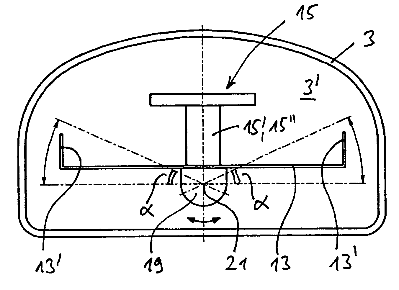
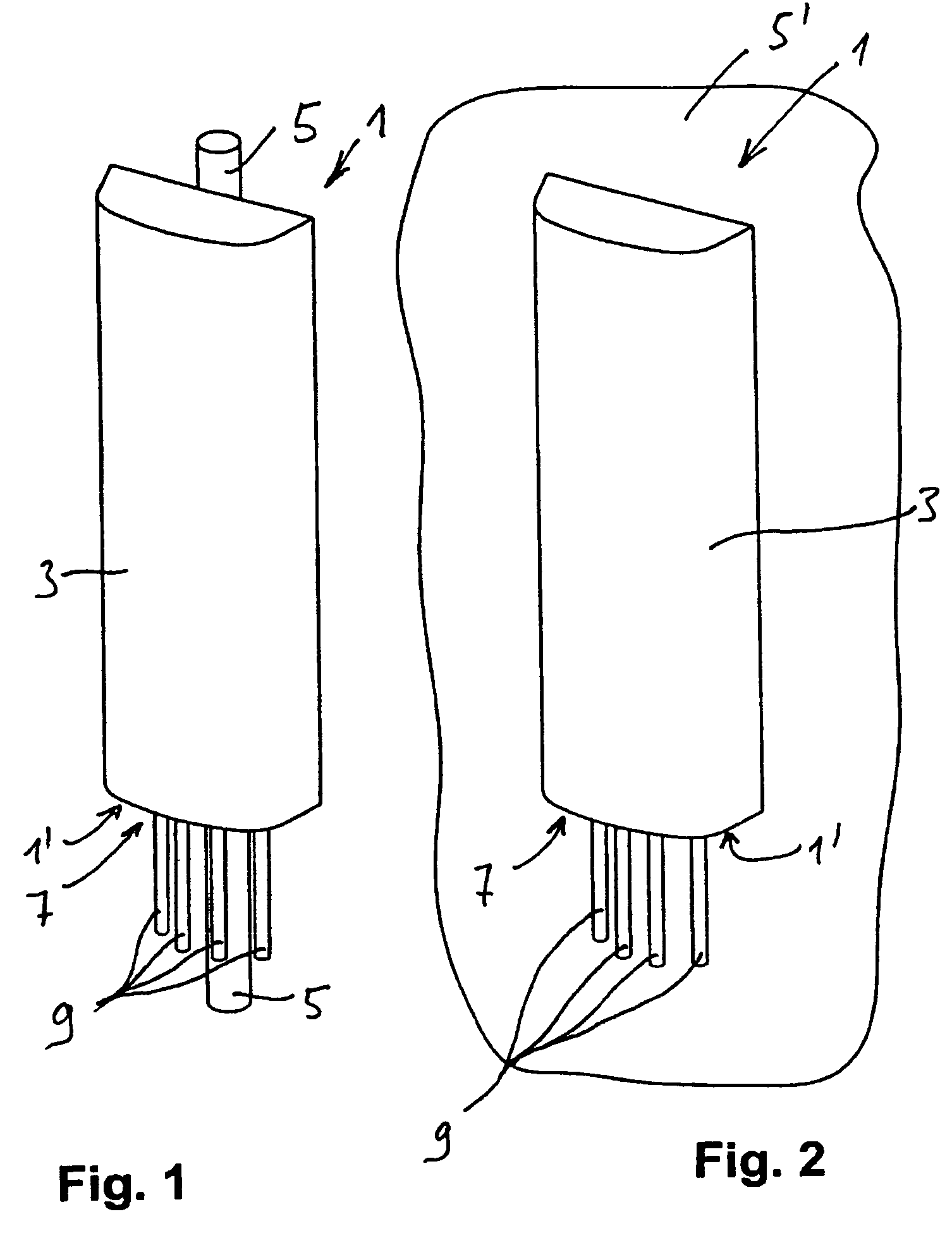
[0030]FIG. 1 shows a schematic perspective illustration of an exemplary illustrative non-limiting antenna arrangement 1, which has a protective housing 3, that is to say a so-called radome, which protects the electrical parts of the antenna device against environmental influences. The antenna arrangement 1 together with the radome 3 is mounted, for example, in the exemplary implementation shown in FIG. 1, on a mount in the form of a vertical post 5.

[0031]A flange 1′ is normally formed on the lower face of the antenna arrangement 1 and two or more connections 7 are provided on this flange 1′. A series of cables 9, in particular supply cables for the antenna elements which are connected to the connects 7, lead to these connections 7.

[0032]In an exemplary illustrative non-limiting arrangement as shown in FIG. 2, the antenna device 1 is mounted on a different mount, that is to say not on a vertical post 5 but, for example, on a vertical wall 5′.

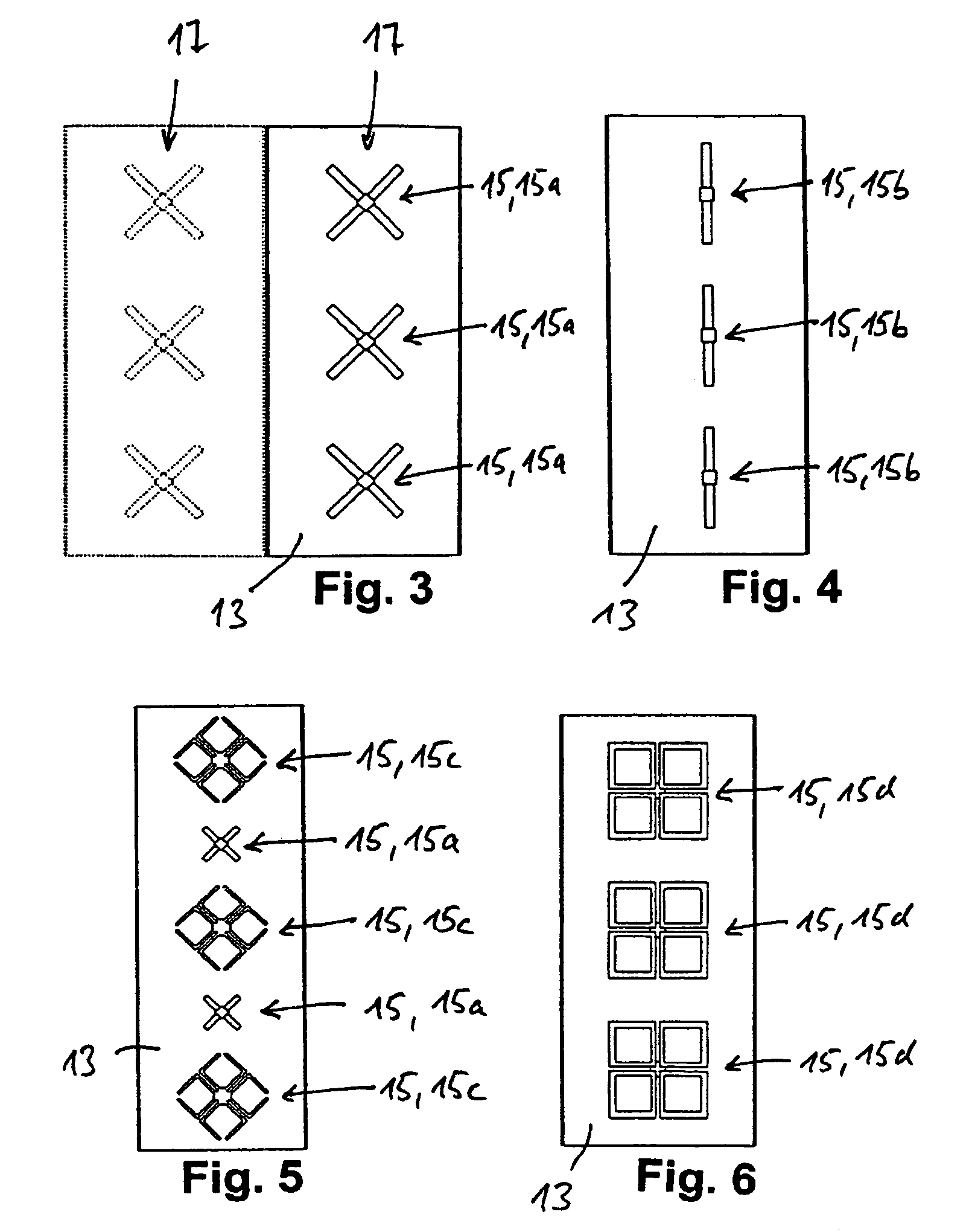
[0033]Widely differing antenna elements an...


PUM


Abstract

A mobile radio antenna arrangement for a base station includes a pivoting device which runs in the longitudinal direction and/or in the vertical direction is provided within the radome. A reflector is at least indirectly held and mounted on the pivoting device. The interior of the radome has dimensions such that the reflector which is located within the radome, and the antenna elements which are provided can be pivoted in the azimuth direction relative to the radome via the pivoting device which is located within the radome.

Description

FIELD[0001]The technology herein relates to a mobile radio antenna arrangement for a base station.BACKGROUND AND SUMMARY[0002]Antennas and antenna arrays, in particular in the form of stationary antenna arrangements for base stations in the mobile radio field, have been known for a long time. Corresponding antenna designs are described, for example, in DE 197 22 742 A1, DE 196 27 015 A1, U.S. Pat. No. 5,710,569 or WO 00 / 39894.[0003]Antenna designs such as these generally have a vertically arranged reflector which can be provided with vertically running webs or edge sections on its two opposite faces on the left and right, with these webs or edge sections generally projecting forwards from the reflector plane. Since more than one antenna element arrangement is generally provided, they are arranged one above the other with a vertical offset.[0004]These may be single-polarized antenna element devices, although they are generally dual-polarized antenna element devices, which can transmi...

Claims


Application Information

Patent Timeline
Patent Type & Authority Patents(United States)
IPC IPC(8): H01Q3/02H01Q1/24H01Q3/00H01Q3/06H01Q21/26
CPCH01Q3/06H01Q1/246
Inventor GOTTL, MAXIMILIANGABRIEL, ROLAND
Owner TELEFON AB LM ERICSSON (PUBL)
Why Eureka
Try Eureka