Optical measurement apparatus and method

a technology of optical measurement and optical probe, applied in the field of modulation spectroscopy, can solve the problems of optical system, background luminescence, scattered luminescence of probe beam, etc., and achieve the effect of optimising reflectance luminescence collection efficiency

Inactive Publication Date: 2006-03-21
OPTICAL METROLOGY PATENTS
View PDF4 Cites 7 Cited by
  • Summary
  • Abstract
  • Description
  • Claims
  • Application Information

AI Technical Summary

Problems solved by technology

A problem in conventional modulation reflectance spectroscopy is that the optical system for collecting the reflected probe beam also collects scattered luminescence which arises as a result of the pump beam incident on the same point of the sample as the probe beam.
As well as interfering with the main signal, background luminescence is also a major factor in the signal-to-noise ratio.

Method used


Image

  • Optical measurement apparatus and method
  • Optical measurement apparatus and method
  • Optical measurement apparatus and method

Examples


Embodiment Construction

Brief Description Of The Drawings

[0026]The invention will be more clearly understood from the following description of some embodiments of the apparatus thereof, given by way of example only with reference to the accompanying drawings in which:

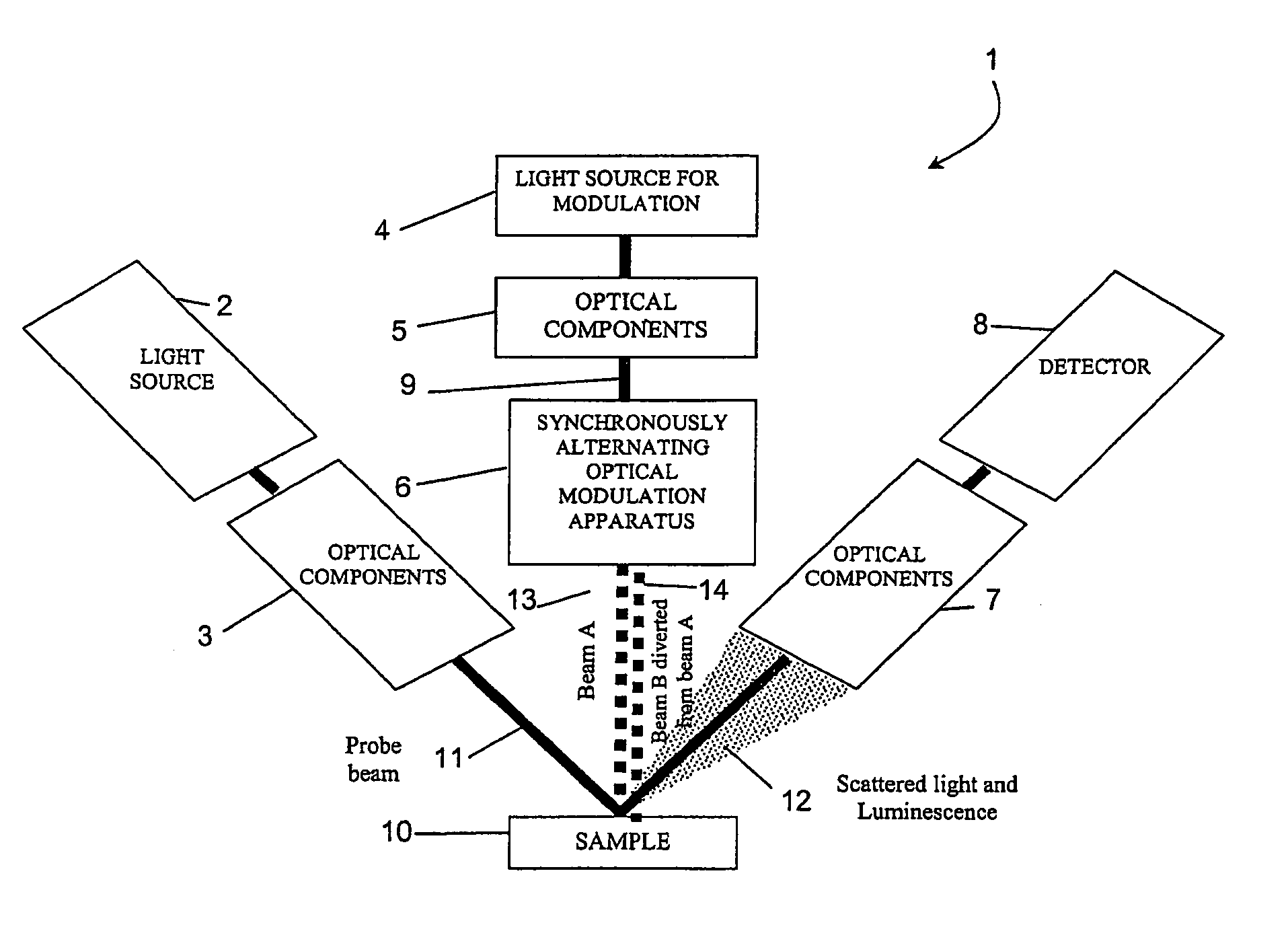
[0027]FIG. 1 shows a diagrammatic view of a modulation spectroscopy system of the invention;

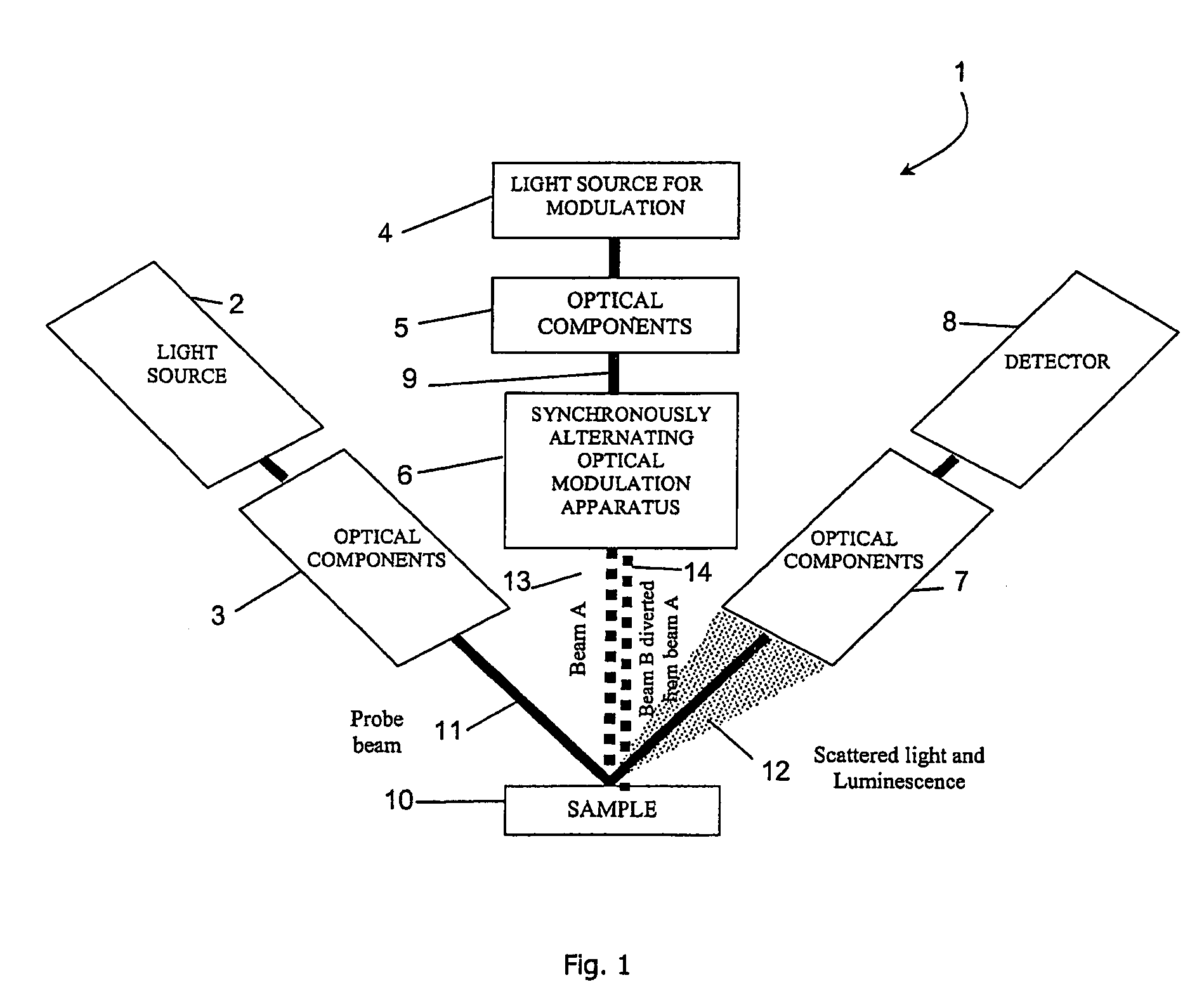
[0028]FIG. 2 is a diagram illustrating operation of the system of FIG. 1; and

[0029]FIG. 3 is a diagrammatic view of another system of the invention.

DESCRIPTION OF THE EMBODIMENTS

[0030]Referring to FIG. 1, a modulation spectroscopy system comprises a probe light source 2 for producing a light beam having a broad spectrum of wavelengths, and beamsteering optical components 3 for shaping the light beam and coupling it to other components. Within the light source 2 a first monochromator disperses the wavelengths of light such that only a narrow range of wavelengths of the light are selected and transmitted. The beamsteering components 3 shape an input light...


PUM

PropertyMeasurementUnit
modulation spectroscopyaaaaaaaaaa
luminescenceaaaaaaaaaa
frequencyaaaaaaaaaa

Abstract

A modulation spectroscopy system (1) directs a probe beam (11) onto a sample (10), the reflected probe beam being collected by a collector (7) and processed by a detector (8). A pump beam generated by a source (4, 5) directs a pump beam (13) onto the sample at the same spot as the probe beam. However, it also switches the pump beam via a path (14) onto an adjacent location not overlapping the probe spot. This is referred to as spatial modulation. A cylindrical lens (16) in the collection subsystem (7) collects reflected light including luminescence from both pump beam spots simultaneously, so that the luminescence becomes a d.c. signal which can be easily eliminated, including means from the modulator for varying pump beam intensities and positions. This provides means to reject the unwanted background luminescence signal as well as improvement to the signal to noise ratio.

Description

[0001]This is a continuation of PCT / IE03 / 000157 filed Nov. 27, 2003 and published in English which in turn is based on provisional Application No. 60 / 429,312 filed Nov. 27. 2002 and Irish Application No. 2002 / 0914 filed Nov. 28, 2002.FIELD OF THE INVENTION[0002]The invention relates to modulation spectroscopy.PRIOR ART DISCUSSION[0003]Modulation spectroscopy is a class of spectroscopy in which the reflectance (or transmission) of a material such as a semiconductor, an organic material, or a polymer is altered at some parts of the electromagnetic spectrum by means of an external perturbation. Generally, this perturbation is applied in a periodic manner, such that the reflectance of the semiconductor at the wavelengths where it changes in response to the external perturbation, periodically alternates between the value in the absence of external perturbation and that which it has in the presence of the external perturbation. In many methods of modulation spectroscopy, the perturbation ...

Claims


Application Information

Patent Timeline
Patent Type & Authority Patents(United States)
IPC IPC(8): G01N21/00G01N21/17
CPCB82Y10/00G01N21/1717B82Y20/00
Inventor MURTAGH, MARTIN EDWARDKELLY, PATRICK VINCENT
Owner OPTICAL METROLOGY PATENTS
Why Eureka
Try Eureka