Timing mark position error correction in self-servo write

Inactive Publication Date: 2006-03-21
HITACHI GLOBAL STORAGE TECH NETHERLANDS BV
View PDF16 Cites 10 Cited by
  • Summary
  • Abstract
  • Description
  • Claims
  • Application Information

AI Technical Summary

Benefits of technology

[0010]Embodiments of the present invention provide a technique to correct timing mark position error in self-servo write (SSW). In specific embodiments, the technique is used to determine and remove the periodic component of the timing mark position error of an SSW pattern. Instead of or in addition to measuring pattern location relative to index (the angular position of a disk with respect to the servo mechanism as determined by the servo pattern mark indicating the start of a sector), a direct measurement of step-to-step misalignment is used. In some embodiments, a direct measurement of step-to-step misalignment includes purposefully misaligned bursts (e.g., by

Problems solved by technology

Ideally, a self-servo pattern should be a line nominally following the arc of motion of the head from the ID to the OD of the disk, but because self-servo writing is basically performed by writing the servo pattern one track at a time and because of the offset between the read sensor and the write element, errors propagate through the servo pattern that cause the servo pattern to be warped away from the desired trajectory, which is nominally straight locally.
To further complicate matters, the periodic error pattern changes as the skew angle of the armature changes.
Thus, the warp can become large enough to cause a low-amplitude misalignment or missed windows during a high-sp

Method used


Image

  • Timing mark position error correction in self-servo write
  • Timing mark position error correction in self-servo write
  • Timing mark position error correction in self-servo write

Examples


Embodiment Construction

[0026]Embodiments of the present invention provide a technique to solve the problem of warps / shifts in the circumferential direction of propagated self-servo writing (SSW) timing and / or index marks. The technique also generally improves self-servo writing / propagation quality. In addition, the present technique provides a way of determining small slippage to the right or left along a circumferential direction on a hard disk drive.

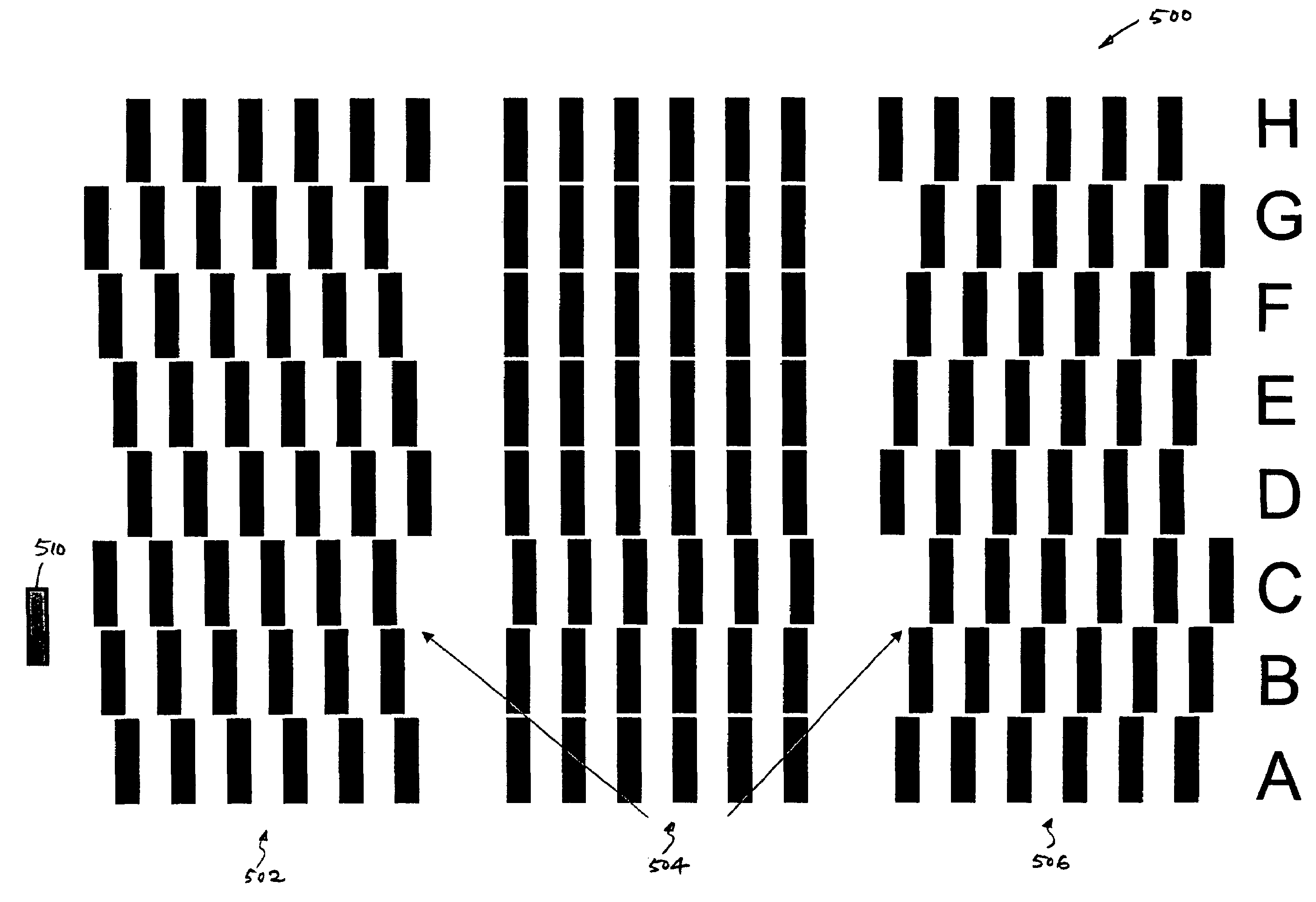
[0027]Timing burst misalignment can be detected by measuring the burst amplitude at a point where the read element overlaps the bursts written on two consecutive steps or tracks, ideally overlapping so that half the signal comes from each of the bursts written on the consecutive steps. If the original neighboring bursts are written at nominally the same phase, small misalignments produce little change in amplitude, with no information on the polarity of the error. If, however, the neighboring bursts are written at a nominal target out-of-phase position, the ...


PUM


Abstract

Embodiments of the present invention provide a technique to correct timing mark position error in self-servo write (SSW). In one embodiment, a method of correcting a timing mark position error of a SSW pattern of a disk drive comprises writing a plurality of timing mark bursts over a plurality of steps on a disk, the plurality of timing mark bursts including at least one misaligned burst having an intentional misalignment in a first step with respect to a corresponding burst in a neighboring second step; reading the misaligned burst and the corresponding burst at a seam between the first step and the second step to obtain a measured burst amplitude; and using the measure burst amplitude to obtain a timing mark position error, which may involve comparing the measured burst amplitude and an expected burst amplitude computed based on the intentional misalignment between the misaligned burst and the corresponding burst to obtain a timing mark position error.

Description

CROSS-REFERENCES TO RELATED APPLICATIONS[0001]This application is related to commonly assigned U.S. patent application Ser. No. 10 / 880,850, filed on Jun. 30, 2004, the entire disclosure of which is incorporated herein by reference.BACKGROUND OF THE INVENTION[0002]This invention relates to disk drives and, more particularly, to a system and method for removing the periodic component of the timing mark position error of a self-servo write (SSW) pattern.[0003]FIG. 1 shows an exemplary hard disk drive (HDD) 100 having a recording slider that includes, for example, an offset head 101, that is positioned over a selected track on a magnetic disk 102 using a servo system for writing data to and / or reading data from the disk 102. Data is recorded in arrays of concentric data information tracks on the surface of the disk 102. While HDD 100 shows only a single magnetic disk 102, HDDs typically have a plurality of stacked, commonly rotated rigid magnetic disks. The servo system of the HDD 100 c...

Claims


Application Information

Patent Timeline
IPC IPC(8): G11B21/10
CPCG11B5/59666G11B5/59633
Inventor SCHULTZ, MARK D.CHAINER, TIMOTHY J.
Owner HITACHI GLOBAL STORAGE TECH NETHERLANDS BV
Why Eureka
Try Eureka