Method for observing object by projection, method for detecting microorganisms and projection detecting system

a technology of object observation and projection, applied in the field of method for observing an object, can solve problems such as difficulty in overlapping of colonies, etc., and achieve the effect of easy obtaining accurate microbial counts

Inactive Publication Date: 2006-03-21
OGAWA HIROYUKI
View PDF21 Cites 41 Cited by
  • Summary
  • Abstract
  • Description
  • Claims
  • Application Information

AI Technical Summary

Benefits of technology

[0009]The method for detecting the presence of microorganisms in a sample comprises the step of preparing a light-permeable culture medium mixed with a sample, illuminating said medium with a coherent laser beam, receiving the light projection generated by said medium with an image sensor. The image sensor generates light projection detect signal when colonies of microorganisms grow large enough to create shades blocking laser beam. The presence of microorganisms is detected by the shades. With said invention of a method for detecting the presence of microorganisms in a sample, microorganisms such as Vibrio alginolyticus, that form transparent colonies, can be detected without staining since the presence of transparent colonies on laser path create ring shaped shades generated by diffraction effect. However, microorganisms such as Vibrio parahaemolyticus, that are stainable by some form of dye such as TTC, may be stained to facilitate microbial detection.
[0013]When the projection detecting system of the fourth invention is used, many sample-containing container cells under observation are placed on multiple loading portions in a row. A sample is mixed with a light-permeable medium and poured into a transparent container cell, for example. A coherent laser beam emitting source illuminates through many sample-and-medium filled container cells placed on said loading portion and an image sensor receives the compounded light projection generated by said samples. When a sample in each container cell forms colonies, they block the laser beam and create shades and produce the projected image data output on each detector of an image sensor. When objects under observation comprise of transparent container cells filled with a sample-containing medium, for instance, and a sample inside of any container cell forms colonies, blocking the laser beam and creating shades which generate the projected image data corresponding to each detector, the presence of microorganisms in one or more container cells is detected. When the presence of microorganisms is detected in samples, if a laser beam individually illuminates sample by sample, then the specific sample creating shades can be identified. With this set-up, microbial detection becomes more efficient especially when number of samples contaminated by microorganisms is small.
[0018]With this invention of a method for detecting the presence of microorganisms in a sample and a projection detecting system, the presence of microorganisms is detected by image sensor so that colonies are detected before they can be seen by naked eye and incubation duration until detection is much shorter. Detecting the presence of microorganisms is also achieved before colonies grow up and overlap each other so that accurate microbial counts can be obtained easily. Furthermore, no troublesome lens focussing is required for microbial detection and all microorganisms in the path of laser beam are detected regardless the depth they locate since microorganisms in a sample are directly projected to image sensor.

Problems solved by technology

However, traditional approach to the microbial counts have involved longer incubation duration since a colony has to be large enough to be counted visually, and a longer incubation often causes colony overlapping and count difficulty or inaccuracy problem when the contamination level in a sample is high.

Method used


Image

  • Method for observing object by projection, method for detecting microorganisms and projection detecting system
  • Method for observing object by projection, method for detecting microorganisms and projection detecting system
  • Method for observing object by projection, method for detecting microorganisms and projection detecting system

Examples


Embodiment Construction

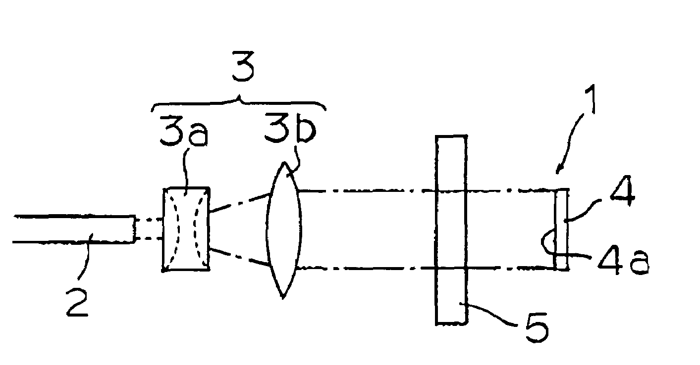
[0029]Using figures, some applications of the present invention are described as follows. FIG. 1 shows first form of application of the present invention.

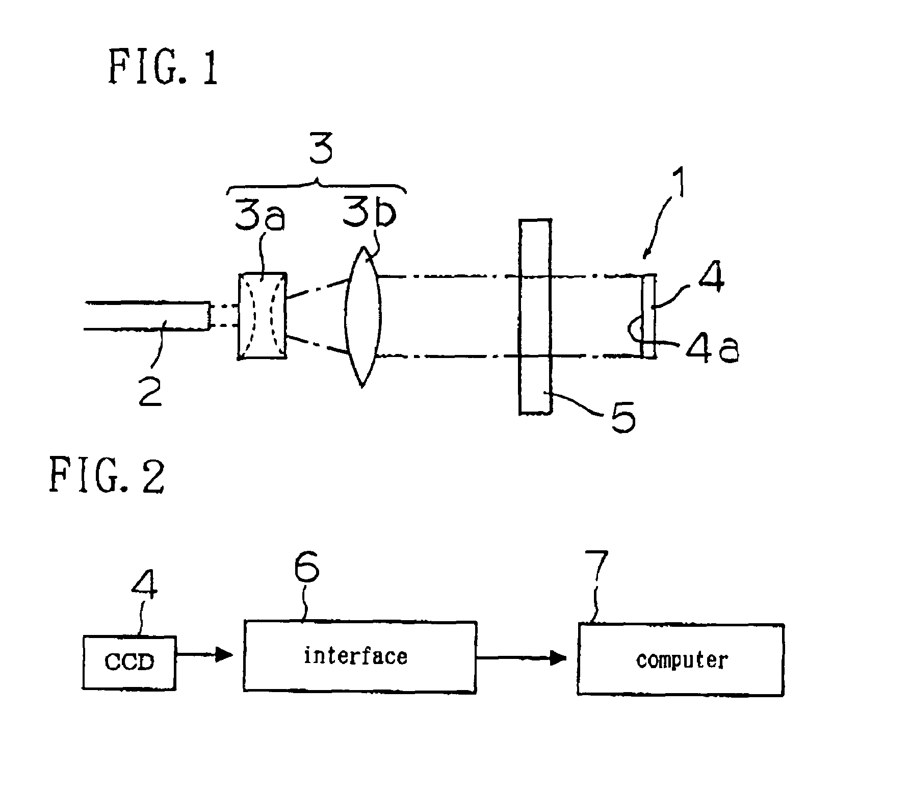
[0030]As FIG. 1 shows, a projection detecting system 1 has a loading portion (not shown in the figure), a laser beam emitting source 2, a beam expander 3 and an image sensor 4.

[0031]A loading portion accommodates a cell 5 (transparent container for light-permeable medium). A cell 5 utilized is transparent, thin and sterilized 10 ml container cell. A loading portion has a capability of incubating the cell 5 at appropriate temperature for microorganisms to grow. Instead of having incubation ability, cell 5 can be made out from a material that heats up by itself to appropriate temperature for microorganisms to grow, receiving laser beam from a laser beam emitting source 2.

[0032]A laser beam emitting source 2 is so arranged to illuminate the cell 5 placed on a loading portion. A white laser is more desirable for a laser beam emitting s...


PUM

PropertyMeasurementUnit
sizeaaaaaaaaaa
sizeaaaaaaaaaa
sizeaaaaaaaaaa

Abstract

Fast microbial detection is accomplished by identifying quantities of microorganisms accurately and easily.A cell 5 is placed on a loading portion. A coherent laser beam source 2 emits laser beam to a cell 5. A CCD area image sensor 4 is an array of light sensitive detectors. An image sensor 4 receives light projection image that passes through a cell 5 illuminated by the beam from a laser beam source 2, generating projection image signals on each light sensitive detectors. The projection image data is fed into a computer and analyzed.

Description

TECHNICAL FIELD[0001]This invention relates to a method for observing an object, a method for detecting microorganisms in a culture medium, and a projection detecting system for an object.BACKGROUND ART[0002]For detecting the presence of such microorganism in food as Escherichia coli, Staphylococcus aureus, Vibrio or the like, that causes food poisoning, food manufacturing companies work on microbial detection. To express a level of contamination, number of living organisms per 1 g or 1 ml in foodstuff is used as an indicator when microbial detection is performed. Standard Methods Agar is widely used in the determination of microbial counts, being incubated at 35° C.±1° C. for 24 or 48 hours. To determine microbial counts, colonies on an agar plate are counted while viewing the agar plate or a colony counter is used for counting. In count methods, a dilution of the sample is mixed in a sterile dish with melted agar and colonies in a medium are counted after the agar is incubated.[00...

Claims


Application Information

Patent Timeline
Patent Type & Authority Patents(United States)
IPC IPC(8): G06K9/00C12M1/34C12Q1/04G01N15/14G01N21/01G01N21/17G01N33/483H04N7/18
CPCC12Q1/04G06K9/00154G01N15/1463G01N2015/1486G06V40/30
Inventor OGAWA, HIROYUKI
Owner OGAWA HIROYUKI
Why Eureka
Try Eureka