Waste container

a technology for storing containers and waste, applied in the field of containers, can solve the problems of damage, and slipping through the gripper of waste containers, and achieve the effect of preventing the waste container from falling

Inactive Publication Date: 2006-03-28
REHRIG PACIFIC CO INC
View PDF44 Cites 101 Cited by
  • Summary
  • Abstract
  • Description
  • Claims
  • Application Information

AI Technical Summary

Benefits of technology

[0005]The present invention provides a waste container including at least one protrusion extending outward from the container and spaced below the lip. The grippers grip the waste containe...

Problems solved by technology

However, while inverted, the waste container may slip through the grippers and become damaged.
Unfortunately, traditionally...

Method used


Image

  • Waste container
  • Waste container
  • Waste container

Examples


first embodiment

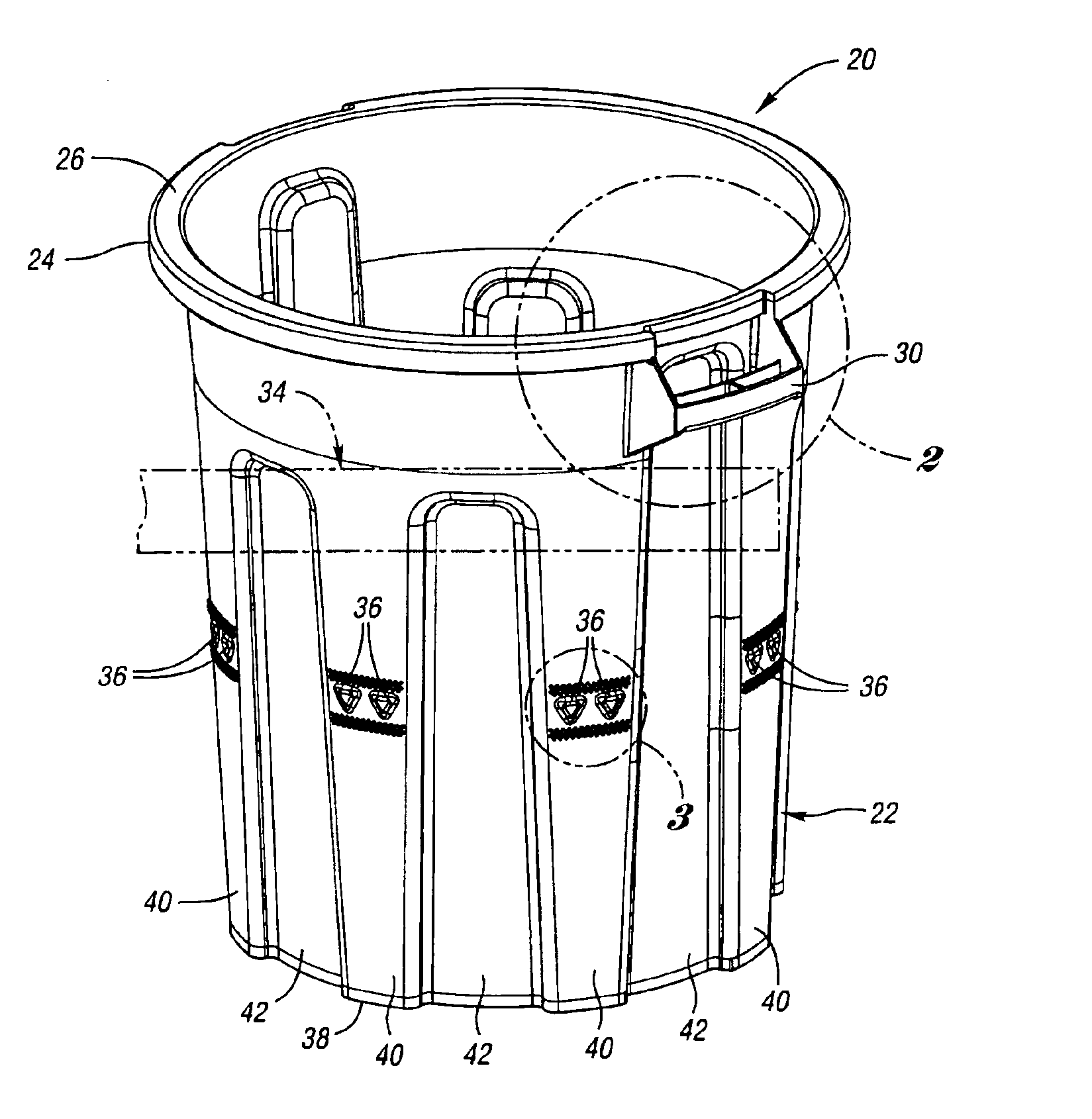
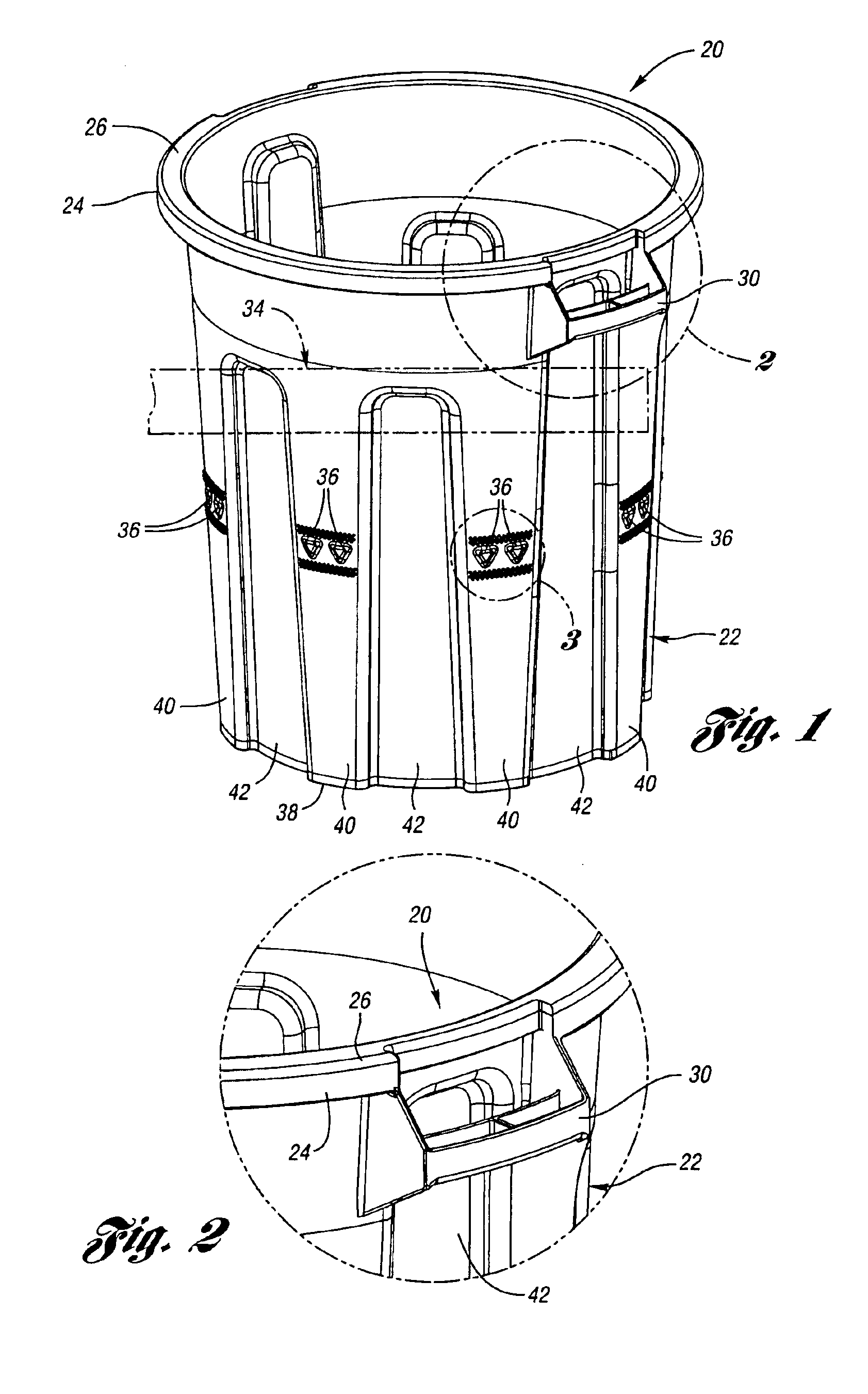
[0017]FIG. 1 illustrates a waste container 20 according to the present invention. The waste container 20 includes a generally cylindrical body wall 22 having a lip 24 protruding radially outward about the circumference of an upper edge 26 of the body wall 22. The waste container 20 further includes a pair of handles 30 (one shown) which also protrude radially outward from the body wall 22. The lip 24 and handles 30 are designed to be engaged by grippers 34 (one shown in phantom) of an automatic lifter on the waste collection truck. If the waste container 20 begins to slip through the grippers 34 while being lifted, the grippers 34 engage the lip 24 and / or handles 30, thereby preventing the waste container 20 from slipping completely through the grippers 34.

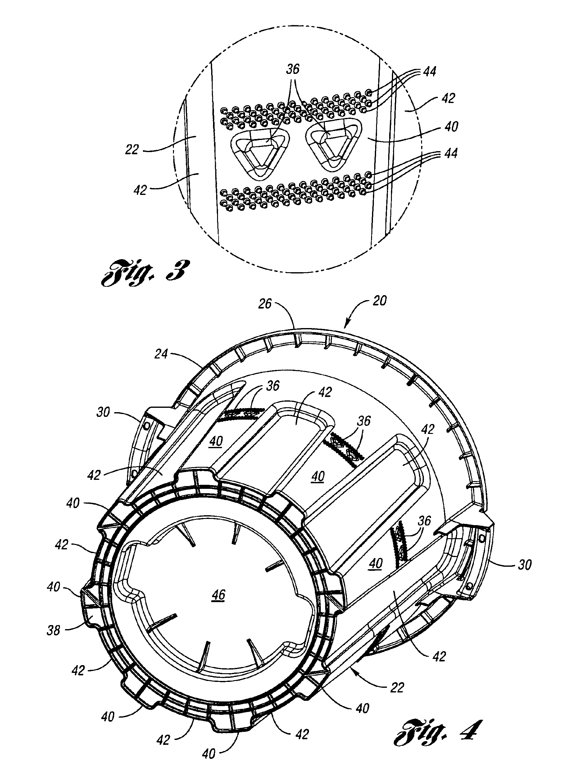
[0018]The present invention also provides a plurality of protrusions 36 formed below the area of engagement by the grippers 34. As shown in FIG. 1, the plurality of protrusions 36 are formed in the body wall 22, approximately midw...

second embodiment

[0022]FIG. 5 illustrates a waste container 60 according to the present invention. The waste container 60 comprises a generally cylindrical body wall 62 having a lip 64 protruding radially outward from an upper edge 66 of the body wall 62. The waste container 60 further includes a pair of handles 70 (one shown) protruding radially outward from the upper edge 66 of the body wall 62. The body wall 62 further includes a portion 72 of increased diameter, thereby providing a circumferential ridge 74. The circumferential ridge 74, lip 64 and / or handle 70 may all engage the grippers 34 when the automatic lifter (not shown) lifts the waste container 60.

[0023]A base portion 76 protrudes radially outwardly about the circumference of the body wall 62 at a lower edge 80 of the body wall 62. The base portion 76 may be integrally molded with the body wall 62 or, as will be described below, may be snap-fit or otherwise removably or non-removably secured to the lower edge 80 of the body wall 62. In ...


PUM


Abstract

A waste container provides at least one protrusion spaced below a lip extending radially outwardly from an upper edge of the waste container. The at least one protrusion is spaced below the lip to permit a gripper from an automatic lifter to grasp the waste container between the at least one protrusion and the upper lip. The at least one protrusion may be a plurality of triangular shaped bosses formed midway between the upper edge and lower edge of the waste container. Alternatively, the at least one protrusion may be a base portion which extends radially outwardly at a lower edge of the waste container. The at least one protrusion prevents the waste container from slipping completely through the grippers while the waste container is inverted while emptying the contents into a truck.

Description

BACKGROUND OF THE INVENTION[0001]The present invention relates generally to containers and more particularly to a waste container for use with automated handling equipment.[0002]Some residential waste collection services have an automatic lifter for lifting and dumping the waste containers into the waste truck. Generally, the lifter includes grippers which grasp the waste container. The lifter then lifts the waste container from the ground and inverts the waste container to dump the contents into the waste truck. The lifter then rotates the waste container back to an upright position and returns the waste container to its original position on the ground.[0003]The waste container includes a lip at an upper end of the waste container which protrudes radially outward from an upper edge of the wall of the waste container. The lip prevents the waste container from slipping through the grippers when the lifter lifts the waste container up off the ground. However, while inverted, the waste...

Claims


Application Information

Patent Timeline
IPC IPC(8): B65F1/02B65D8/12B65F1/12
CPCB65F1/122Y10S220/908B65F1/02
Inventor GRUBER, ROBERT V.HASSELL, JON P.
Owner REHRIG PACIFIC CO INC
Why Eureka
Try Eureka