Modular ankle-foot orthosis

Inactive Publication Date: 2006-03-28
PRESSMAN MARTIN M +1
View PDF24 Cites 31 Cited by
  • Summary
  • Abstract
  • Description
  • Claims
  • Application Information

AI Technical Summary

Benefits of technology

[0022]The present invention comprises a series of embodiments of a modular ankle and foot orthosis in which the lower leg and ankle component and the plantar support component may be quickly and easily disassembled from or reassembled with one another, as required. The present orthotic allows a patient to wear both components assembled together

Problems solved by technology

A number of conditions exist which adversely affect the foot and ankle of the human body.
A problem which occurs consistently with the various devices of the prior art, is that they tend to be relatively specialized and limited in their versatility.
Yet, the entire assembly (or its components) is sufficiently thin to allow for wear within a shoe, boot, or the like.
Moreover, the essentially monolithic nature of the sole platform and upward extending ankle brace precludes disassembly for modular use.
Brewer does not provide any integral hind foot support or removable plantar orthotic component in his ankle protector.
The sole plate results in the DeToro

Method used


Image

  • Modular ankle-foot orthosis
  • Modular ankle-foot orthosis
  • Modular ankle-foot orthosis

Examples


first embodiment

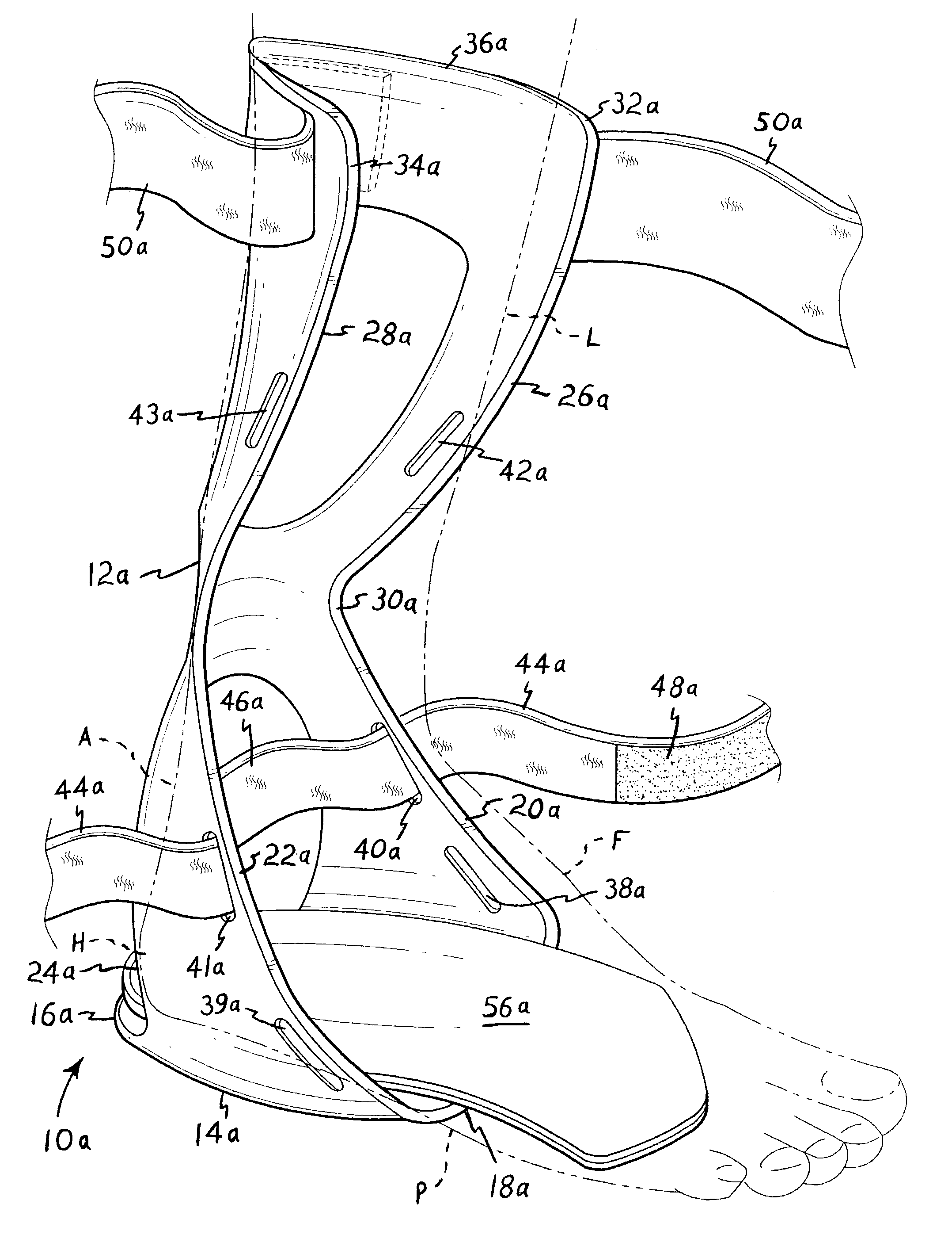
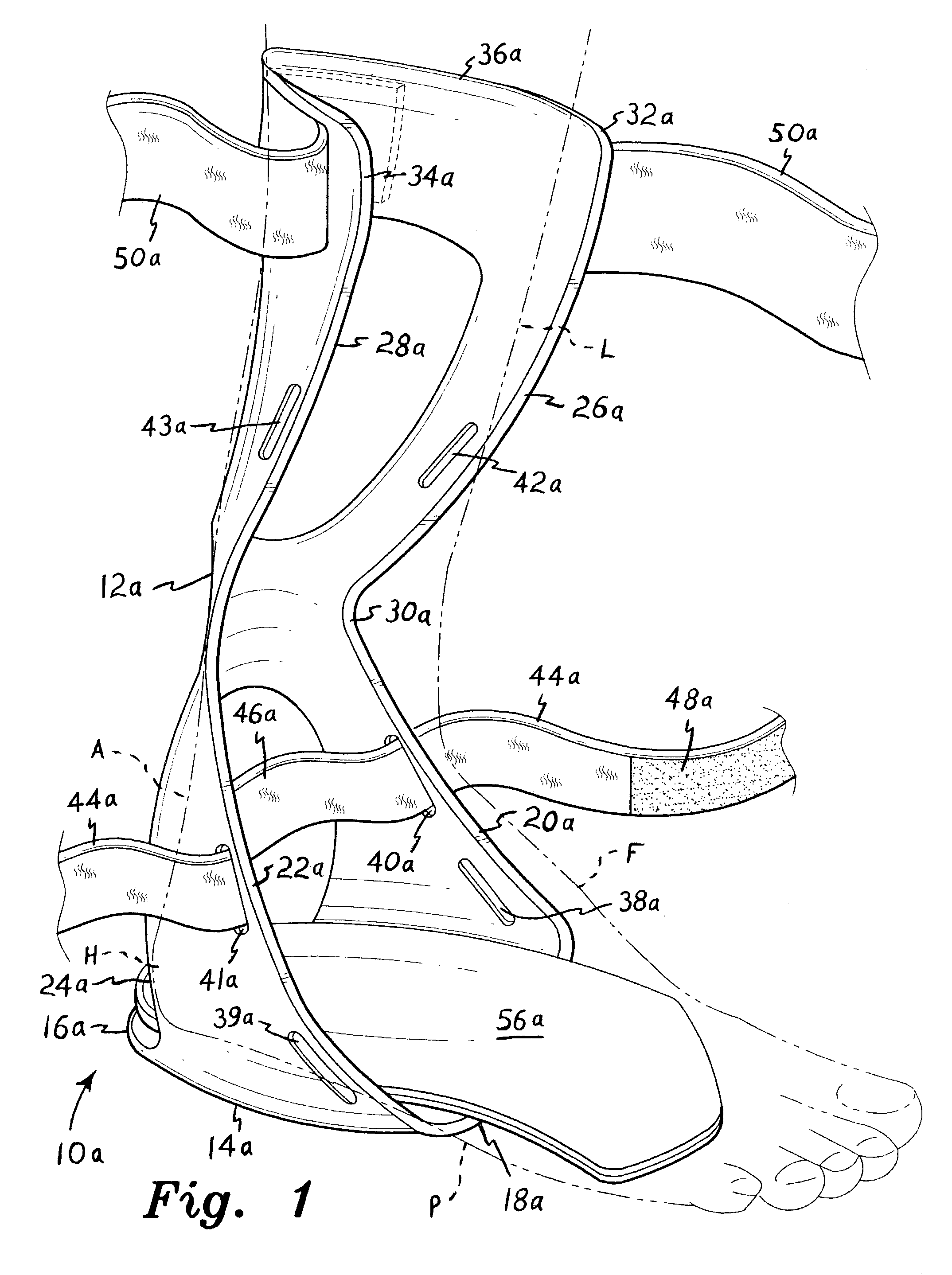
[0040]FIG. 1 illustrates the present modular ankle and foot orthosis assembly, designated by the reference character 10a. The orthosis 10a is separable into two basic components, as noted above. The larger component comprises a lower leg and / or ankle support or brace 12a. preferably formed as a unitary, monolithic structure of a thin, lightweight, and somewhat flexible plastic material (e.g., polypropylene, Nylon®, etc.). The lower leg and ankle component 12a includes a rear foot support plate portion 14a, which resides beneath the heel H or rear foot portion of a patient using the present invention. The lower leg L, foot F, ankle area A, heel H, and plantar or sole portion P of the foot F of a patient or other person wearing or using the present orthosis, are illustrated in broken lines in FIGS. 1 and 3 of the drawings. The rear foot or heel support portion 14a is relatively short, with the rearward end 16a residing beneath or slightly rearwardly of the extreme rearward end of the ...

second embodiment

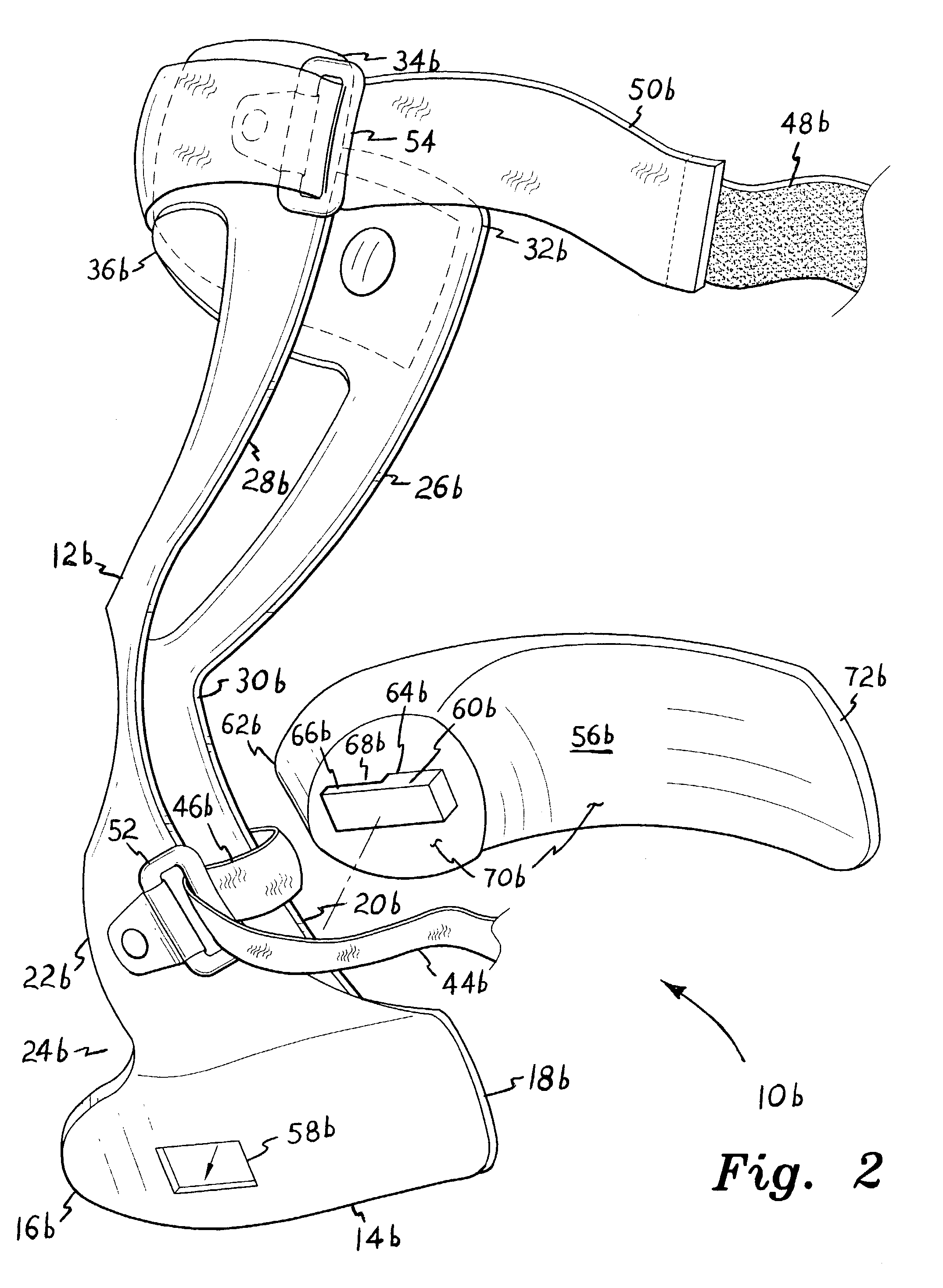
[0043]FIG. 2 is an exploded, bottom and right side perspective view of the present modular ankle-foot orthosis, designated as orthosis assembly 10b. The orthosis 10b of FIG. 2 differs from the orthosis 10a of FIG. 1, primarily in the arrangement of the lower leg, ankle and foot attachment straps. The rear foot support plate 14b of the orthosis 10b of FIG. 2 is also slightly longer than the short support plate 14a of the orthosis 10a of FIG. 1, but the rear foot support plate may be formed to any practicable length as required, depending upon the specific treatment to be applied by the device. Otherwise, the orthosis 10b of FIG. 2 is essentially identical to the orthosis 10a of FIG. 1, with corresponding components 12 through 36 being designated by a letter “b” suffix (i.e., 12b, 14b, etc.), rather than the letter “a” suffix used in describing the components of the orthosis 10a of FIG. 1.

[0044]Rather than providing a series of strap attachment slots, as in the orthosis 10a of FIG. 1,...


PUM


Abstract

A modular ankle-foot orthosis includes a lower leg and ankle support and a plantar foot support. The two components may be secured together to provide more complete support for a patient, as required. The two supports may be attached in various ways, such as a bottom heel clip extending from the foot support component, which secures through a passage in the heel of the lower leg and ankle support component. A tongue extends from the foot support clip, to capture the material at the edge of the lower leg and ankle support passage between the tongue and the foot support plate. The two components are quickly and easily assembled together and disassembled as required, to provide more versatile treatment for the patient. The complete structure, or any components thereof, is sufficiently thin to allow wear within a conventional walking shoe or the like.

Description

BACKGROUND OF THE INVENTION[0001]1. Field of the Invention[0002]The present invention relates generally to orthopedic and orthotic braces and supports, and more specifically to a modular orthotic device or orthosis which selectively serves as an ankle and foot brace or support when the two components are assembled together, or as a foot support when the plantar support component is used separately.[0003]2. Description of the Related Art[0004]A number of conditions exist which adversely affect the foot and ankle of the human body. As a result, the medical fields of podiatry and chiropody have been developed in response to the various ailments and problems which can occur with the feet, or more generally with the lower extremities of the legs. A number of the various ailments and problems which can occur with the feet and lower extremities respond well to treatment using various braces, supports, and other orthotic devices. Accordingly, a number of braces, supports, and similar device...

Claims


Application Information

Patent Timeline
IPC IPC(8): A61F5/00A61F5/01
CPCA61F5/0111
Inventor PRESSMAN, MARTIN M.BURNS, MICHAEL
Owner PRESSMAN MARTIN M
Why Eureka
Try Eureka