Bone implants and methods

a technology of bone implants and bone marrow, applied in the field of bone implants, can solve the problems of persistent pain, pain and disability of a large segment of the population,

Inactive Publication Date: 2006-03-28
ZIMMER SPINE INC
View PDF166 Cites 475 Cited by
  • Summary
  • Abstract
  • Description
  • Claims
  • Application Information

AI Technical Summary

Problems solved by technology

Chronic back problems cause pain and disability for a large segment of the population.
When the disc material is diseased, the opposing vertebrae may be inadequately supported, resulting in persistent pain.

Method used


Image

  • Bone implants and methods
  • Bone implants and methods
  • Bone implants and methods

Examples


Embodiment Construction

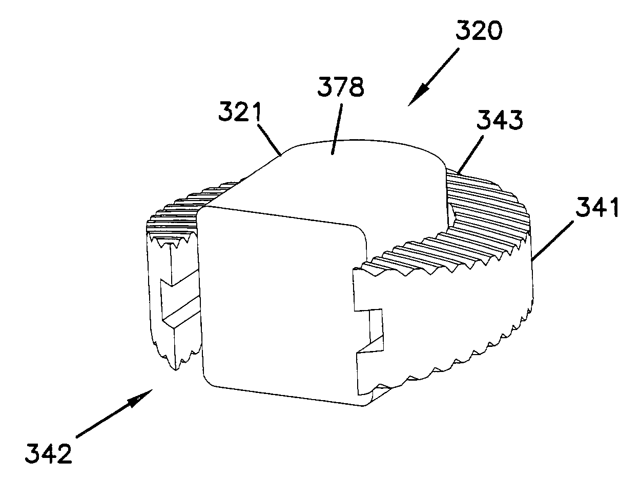
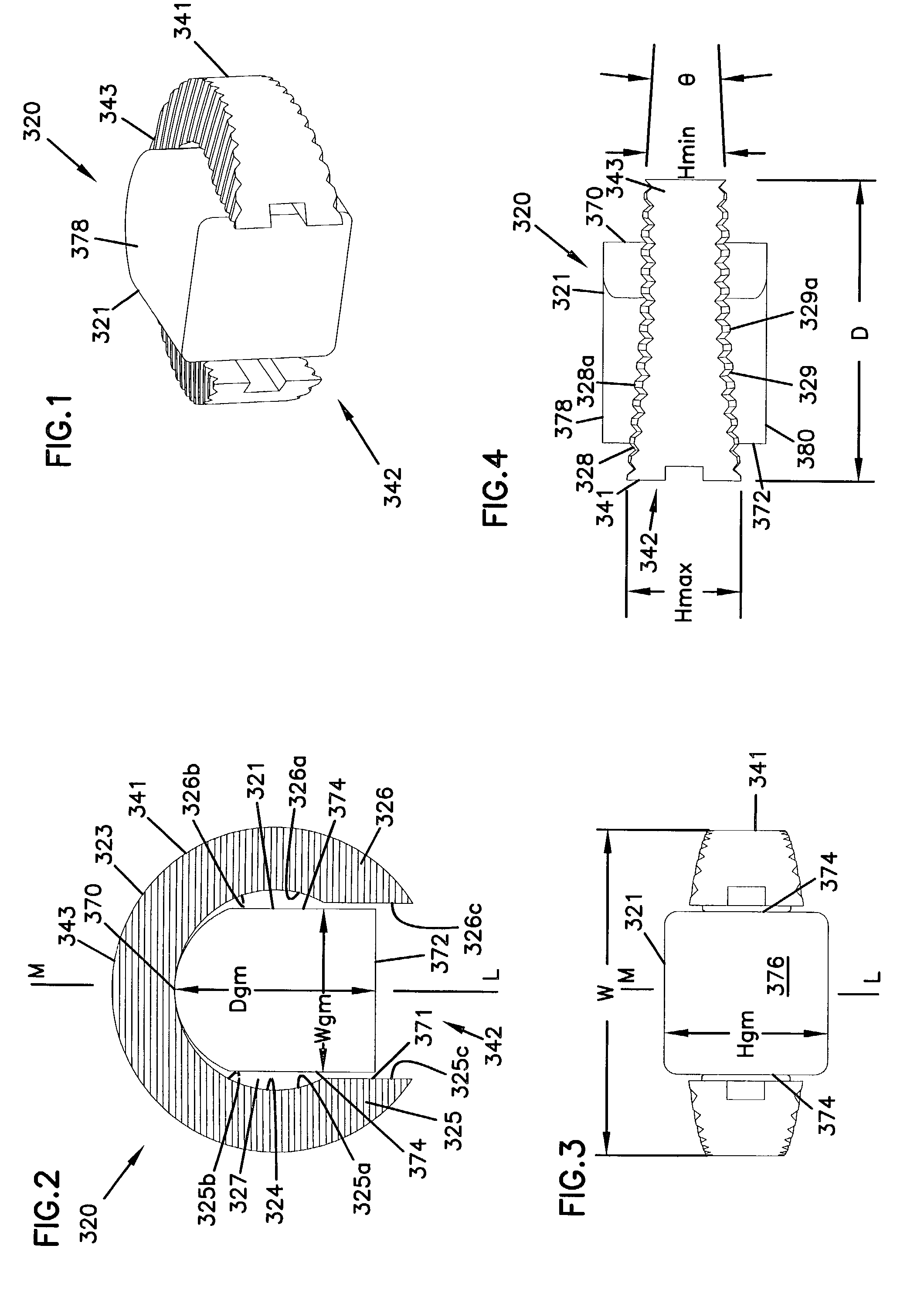
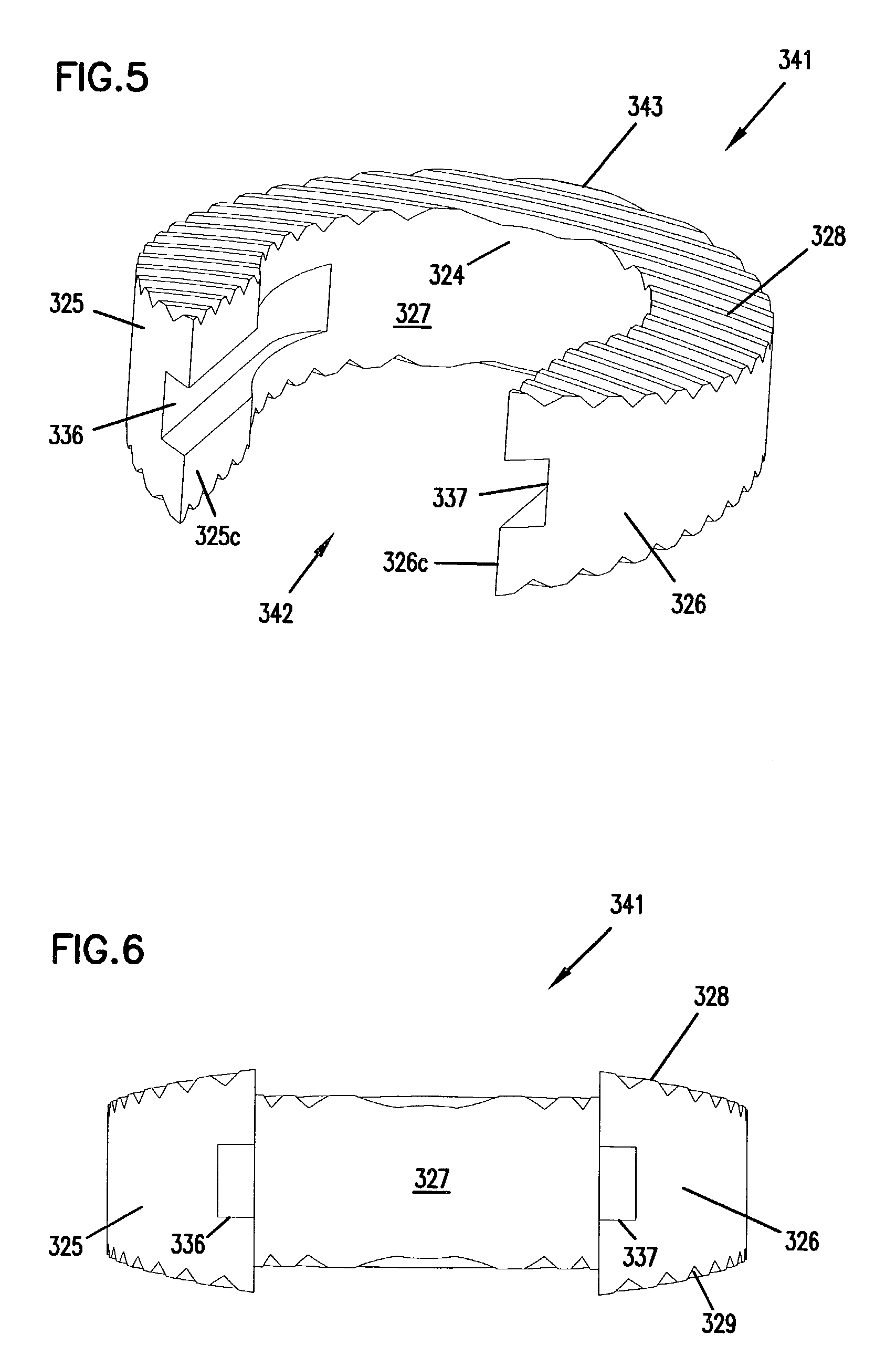
[0059]The present invention is directed toward the fusion of bones. The invention provides natural and / or synthetic bone implants that can function as a bone graft between adjacent bones to be fused. The implants of the invention include unique arrangements, configurations and components to facilitate fusion and maintain stability during the fusion process.

[0060]The implants, instruments and methods of the invention can be used in a variety of bone fusion procedures. In some embodiments, the invention may be particularly advantageous for intervertebral stabilization or arthrodesis of the intervertebral disc space between adjacent vertebrae. Accordingly, for purposes of description herein, the invention will be described by reference to intervertebral fusion procedures in the lumbar region of the spine. However, this description is for exemplary purposes only and should not be construed to limit the intended scope of use of the disclosed implants, instruments or methods. For example,...


PUM


Abstract

Implants, instruments and methods for bone fusion procedures are disclosed. In some embodiments, the implants are particularly advantageous for use between opposing vertebral bodies to facilitate stabilization or arthrodesis of an intervertebral joint. The implants include, at least, a support component that provides structural support during fusion. In a typical embodiment, the implants also include a growth component. A growth component provides an environment conducive to new bone growth between the bones being fused. Several unique configurations to enhance fusion, instruments for insertion and methods for insertion are also disclosed.

Description

CROSS-REFERENCE TO RELATED APPLICATIONS[0001]This application claims the benefit of U.S. Patent Application 60 / 269,777, filed on Feb. 16, 2001, and is a continuation-in-part of U.S. patent application Ser. No. 09 / 896,926, filed on Jun. 28, 2001, now U.S. Pat. No. 6,635,060. U.S. patent application Ser. No. 09 / 896,926 is a continuation-in-part of U.S. patent application Ser. No. 09 / 611,237 filed Jul. 6, 2000, now U.S. Pat. No. 6,641,582.FIELD OF THE INVENTION[0002]This invention pertains to bone implants, instruments and procedures. Specifically, the invention provides bone implants, instruments and methods to facilitate fusion of bone. The invention is particularly suited for stabilization or fusion of the intervertebral disc space between adjacent vertebrae.BACKGROUND OF THE INVENTION[0003]Chronic back problems cause pain and disability for a large segment of the population. Frequently, the cause of back pain is traceable to diseased disc material between opposing vertebrae. When t...

Claims


Application Information

Patent Timeline
Patent Type & Authority Patents(United States)
IPC IPC(8): A61F2/44A61B17/02A61B17/16A61B17/17A61F2/00A61F2/30A61F2/46
CPCA61B17/1671A61B17/1757A61F2/4465A61F2/4611A61B17/1604A61F2250/0063A61B17/1735A61B2017/0256A61F2/442A61F2002/30131A61F2002/30383A61F2002/30599A61F2002/30747A61F2002/3082A61F2002/30879A61F2002/30892A61F2002/30904A61F2002/4475A61F2002/4624A61F2220/0025A61F2230/0013A61B17/1659A61F2/30744A61F2/4603A61F2002/30593
Inventor HANSON, DAVID A.LONGHINI, ROSS A.MCPHILLIPS, DANIEL D.SEME, STEVEN J.
Owner ZIMMER SPINE INC
Why Eureka
Try Eureka