Selectively Expanding Spine Cage, Hydraulically Controllable In Three Dimensions For Enhanced Spinal Fusion
What is Al technical title?
Al technical title is built by PatSnap Al team. It summarizes the technical point description of the patent document.
a spine cage and fusion technology, applied in the field of spinal fusion enhancement, can solve the problems of inability to expand and distract the endplates, existing static cages do not reliably improve the space for neural elements, and the limitations of existing devices for interbody stabilization are important and significan
Active Publication Date: 2011-11-03
HOWMEDICA OSTEONICS CORP
View PDF2 Cites 63 Cited by
Summary
Abstract
Description
Claims
Application Information
AI Technical Summary
This helps you quickly interpret patents by identifying the three key elements:
Problems solved by technology
Method used
Benefits of technology
[0017]In one implementation, the present disclosure is directed to an apparatus for providing spinal correction in three dimensions. The apparatus comprises a selectively expanding spinal implant for insertion between first and second vertebrae of a patient, said spinal implant
Problems solved by technology
Such existing devices for interbody stabilization have important and significant limitations.
These limitations include an inability to expand and distract the endplates.
Current interbody spacers do not maintain interbody lordosis and can contribute to the formation of a straight or even kyphotic segment and the clinical problem of “flatback syndrome.” Separation of the endplates increases space available for the neural elements, specifically the neural foramen.
Existing static cages do not reliably improve space for the neural elements.
Poor Interface between Bone and Biomaterial
Another problem with conventional devices of interbody stabilization includes poor interface between bone and biomaterial.
Another problem of conventional interbody spacers is their large diameter requiring wide exposure.
30 Conventional devices have significant limitation with regard to safety and efficacy.
Regarding safety of the interbody spacers, injury to neural elements may occur with placement from an anterior or posterior approach.
A conventional spine cage lacks the ability to expan
Method used
Image
Click on the blue label to locate the original text in one second.
Reading with bidirectional positioning of images and text.
Examples
Embodiment Construction
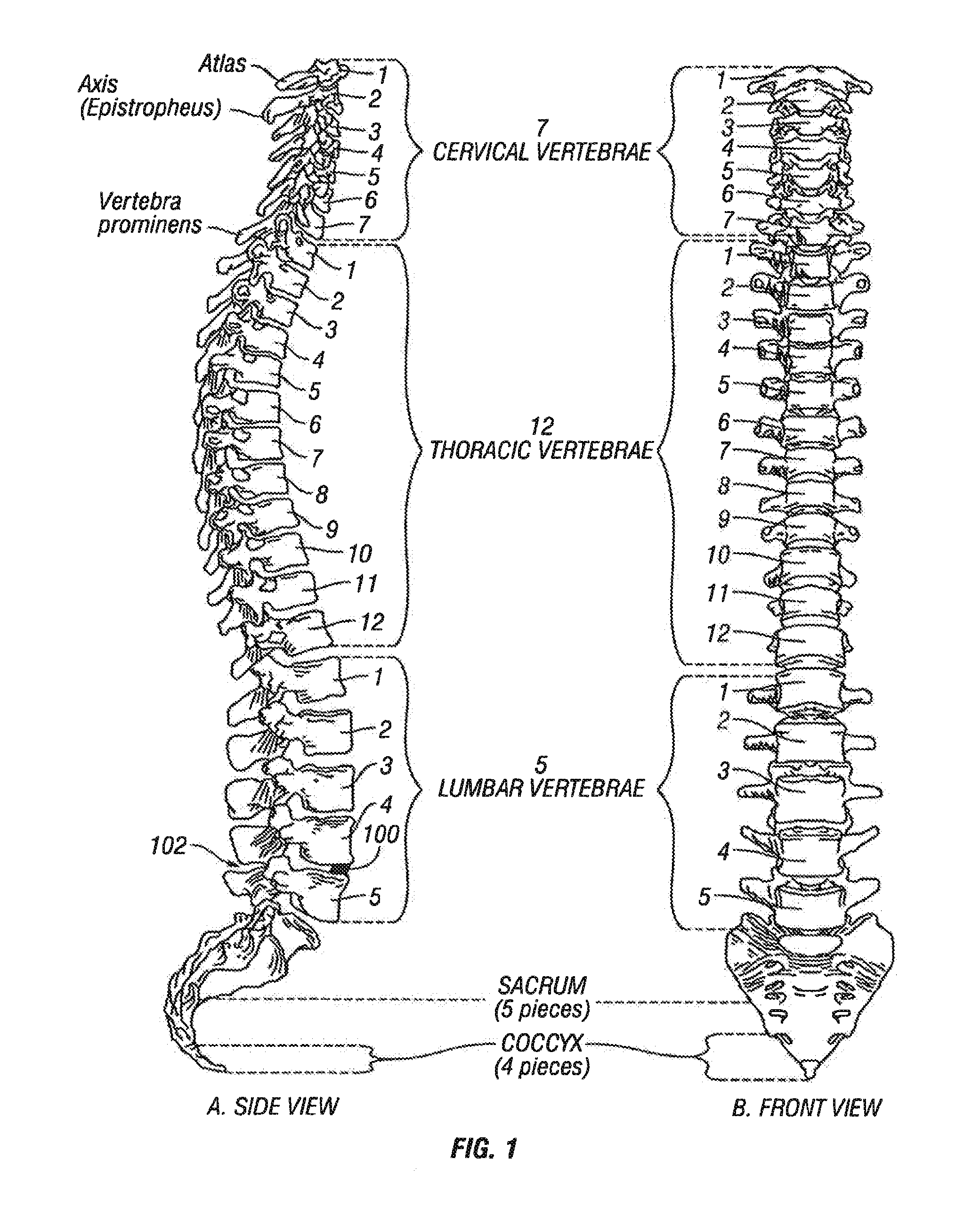
[0043]Referring to FIG. 1, vertebral segments or end plates are shown with an average 8 mm gap representing an average intervertebral space. A complete discectomy is performed prior to the insertion of the SEC 100. The intervertebral disc occupying space 102 is removed using standard techniques including rongeur, curettage, and endplate preparation to bleeding subcondral bone. The posterior longitudinal ligament is divided to permit expansion of the intervertebral space.
[0044]The intervertebral space 102 is distracted to about 10 mm using a rotating spatula (Not shown. This is a well-known device that looks like a wide screw driver that can be placed into the disc space horizontally and turned 90 degrees to separate the endplates).
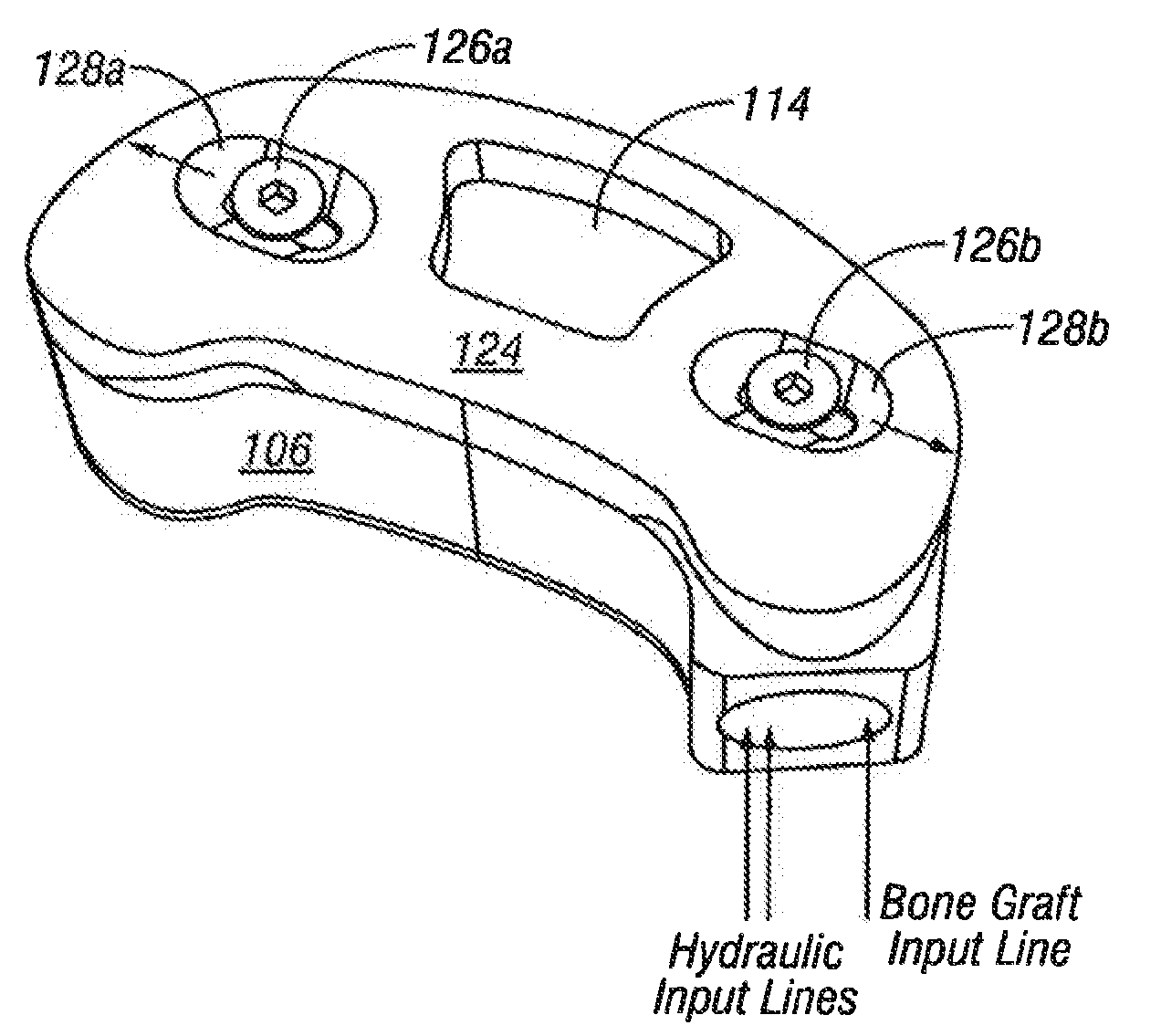
[0045]The SEC is inserted posteriorly (in the direction of arrow 102 between the no. 4 and 5 lumbar vertebrae as shown in FIG. 1 (lateral view) or into any selected inververbral space. In accordance with an aspect of the invention, the SEC is reduced to sm...
PUM
Property
Measurement
Unit
Force
aaaaa
aaaaa
Mass
aaaaa
aaaaa
Diameter
aaaaa
aaaaa
Abstract
A selectively expanding spine cage has a minimized diameter in its unexpanded state that is smaller than the diameter of the neuroforamen through which it passes in the distracted spine. The cage conformably engages between the endplates of the adjacent vertebrae to effectively distract the anterior disc space, stabilize the motion segments and eliminate pathologic spine motion. Angular deformities can be corrected, and natural curvatures restored and maintained. The cage enhances spinal arthrodesis by creating a rigid spine segment, or if filled with compressible substances, the cage can be used for motion preservation between vertebral bodies. Expanding selectively (anteriorly, along the vertical axis of the spine) rather than uniformly, the cage height increases and holds the vertebrae with fixation forces greater than adjacent bone and soft tissue failure forces in natural lordosis. Stability is thus achieved immediately, enabling patient function by eliminating painful motion. The cage shape intends to rest proximate to the anterior column cortices securing the desired spread and fixation, allowing for bone graft in, around, and through the implant for arthrodesis whereas for arthroplasty it fixes to endpoints but cushions the spine naturally.
Description
RELATED APPLICATION DATA[0001]This application is a continuation of U.S. patent application Ser. No. 11 / 535432, filed Sep. 26, 2006, and titled “Selectively Expanding Spine Cage, Hydraulically Controllable in Three Dimensions for Enhanced Spinal Fusion,” now allowed, which claims the benefit of priority of U.S. Provisional Patent Application Ser. No. 60 / 720,784, filed Sep. 26, 2005, and titled “Selectively Expanding Spine Cage, Hydraulically Controllable In Three Dimensions for Enhanced Spinal Fusion,” which are incorporated by reference herein in their entirety.[0002]This application is also related to U.S. patent application Ser. No. 11 / 981,150, filed Oct. 31, 2007, and titled “Selectively Expanding Spine Cage, Hydraulically Controllable in Three Dimensions for Enhanced Spinal Fusion,” now pending, U.S. patent application Ser. No. 11 / 981,452, filed Oct. 31, 2007, and titled “Selectively Expanding Spine Cage, Hydraulically Controllable in Three Dimensions for Vertebral Body Replace...
Claims
Application Information
Patent Timeline
Application Date:The date an application was filed.
Publication Date:The date a patent or application was officially published.
First Publication Date:The earliest publication date of a patent with the same application number.
Issue Date:Publication date of the patent grant document.
PCT Entry Date:The Entry date of PCT National Phase.
Estimated Expiry Date:The statutory expiry date of a patent right according to the Patent Law, and it is the longest term of protection that the patent right can achieve without the termination of the patent right due to other reasons(Term extension factor has been taken into account ).
Invalid Date:Actual expiry date is based on effective date or publication date of legal transaction data of invalid patent.