Musical tone control apparatus and sensing device for electronic musical instrument

a technology of electronic musical instruments and tone control apparatus, which is applied in the direction of instruments, electrophonic musical instruments, instruments, etc., can solve the problems of conventional instruments lacking fidelity as foot motion input devices or input interfaces, and the sensor units suffering from problems

Inactive Publication Date: 2006-03-28
YAMAHA CORP
View PDF18 Cites 16 Cited by
  • Summary
  • Abstract
  • Description
  • Claims
  • Application Information

AI Technical Summary

Problems solved by technology

Such a sensor unit suffers from a problem as follows:
In addition, the conventional musical tone control apparatus employs an insole-type foot sensor, so it suffers from a problem as follows:
In other words, the conventional apparatus lacks fidelity as an input device (or input interface) of the foot motion.

Method used


Image

  • Musical tone control apparatus and sensing device for electronic musical instrument
  • Musical tone control apparatus and sensing device for electronic musical instrument
  • Musical tone control apparatus and sensing device for electronic musical instrument

Examples


embodiment 1

[A] Embodiment 1

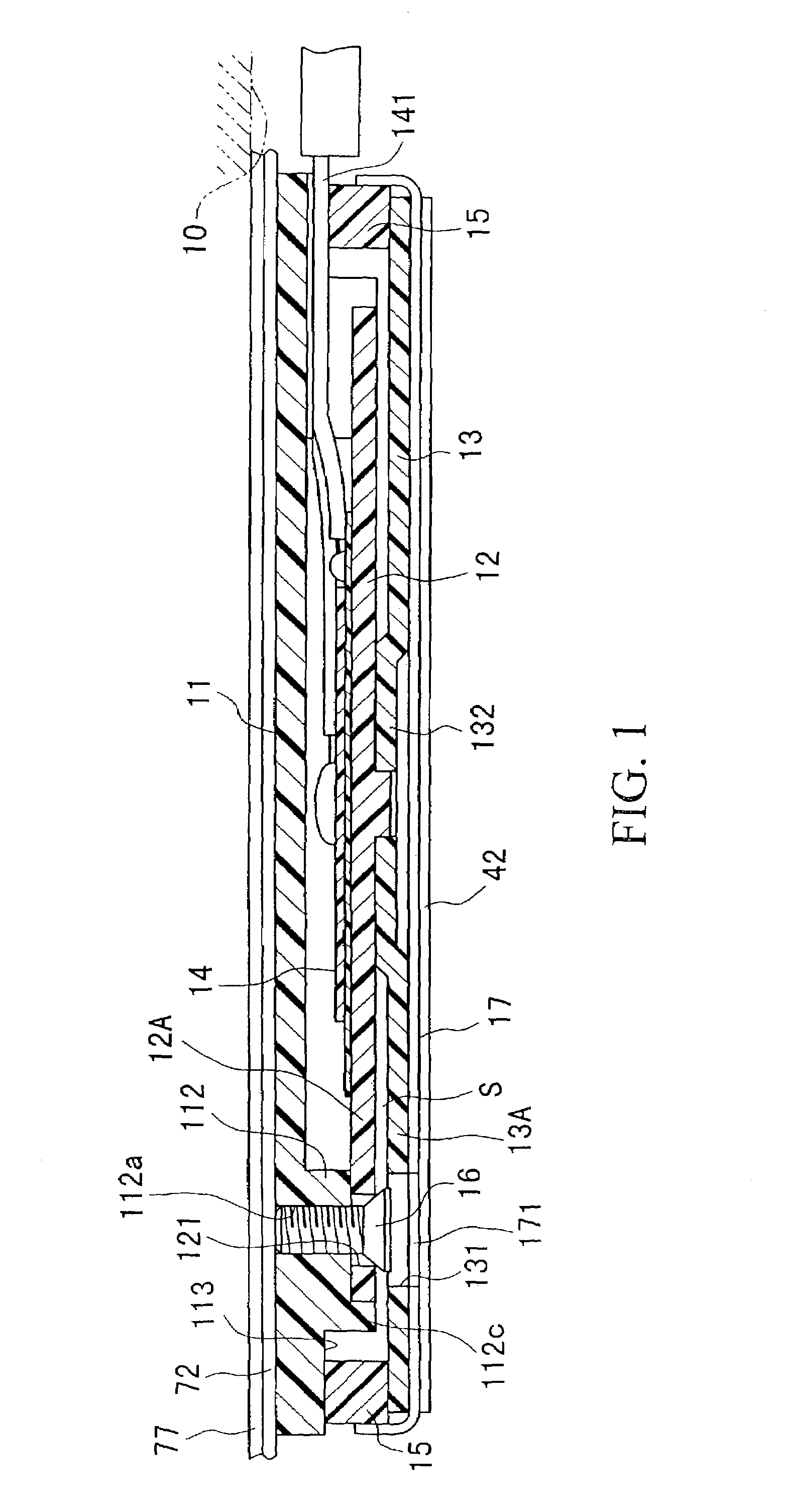
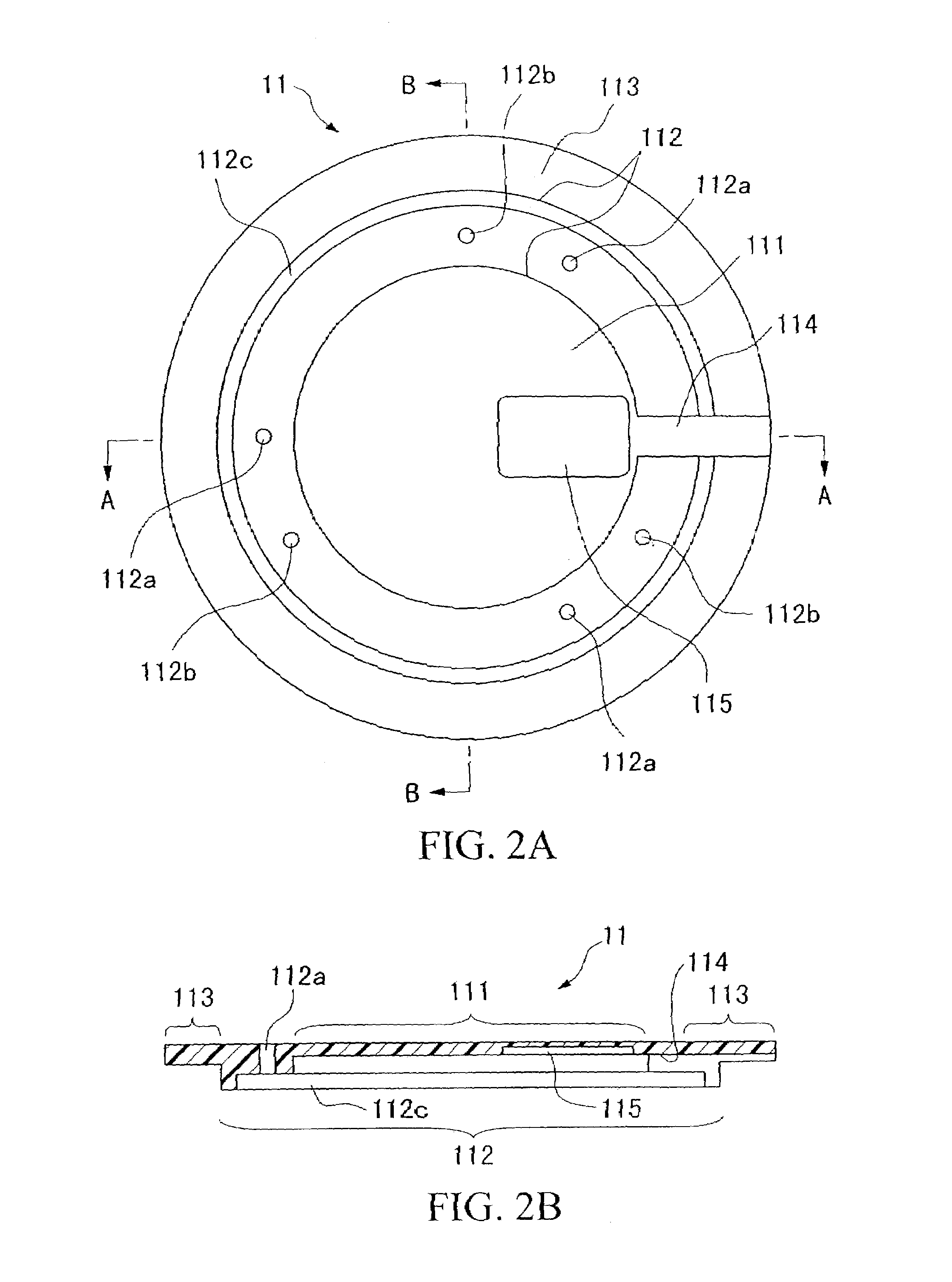
[0052]FIG. 1 is a traverse sectional view showing a sensing device for an electronic musical instrument in accordance with embodiment 1 of the invention. Herein, the sensing device is constructed by a sensor case which contains a piezoelectric sensor, a sensor fixing member and a disc plate pressure member. FIG. 2A is a bottom view of the sensor case, while FIG. 2B is a view in cross section of the sensor case taken along the line A—A in FIG. 2A. In addition, FIG. 3A is a bottom view showing the sensor fixing member and disc plate pressure member which are assembled together, while FIG. 3B is a view in cross section of the sensor fixing member and disc plate pressure member taken along the line A—A in FIG. 3A. The sensing device for the electronic musical instrument as a whole is constructed to have a cylinder-like shape which is “flat” and “thin”. That is, a sensor case 11 covering the sensing device is fixed to a main body of an input device, e.g., a floor facing p...

embodiment 2

[B] Embodiment 2

[0073]Next, a description will be given with respect to shoe-type musical tone control apparatuses in accordance with embodiment 2 of the invention. Herein, the shoe-type musical tone control apparatus is designed to be attached to a footwear like a shoe. FIG. 7 is a side view partially in section showing a first example of the shoe-type musical tone control apparatus. FIG. 8 is a bottom view partially in section showing the shoe-type musical tone control apparatus. In the shoe-type musical tone control apparatus shown in FIG. 7 and FIG. 8, sensing units 21 and 22 each containing a piezoelectric sensor are attached respectively to a toe portion and a heel portion of the floor facing portion (i.e., sole) 10 of a shoe 100.

[0074]Each of the sensing units 21 and 22 corresponds to the foregoing sensing device for the electronic musical instrument. Herein, a vibration input is applied to the sensing units 21 and 22 in any directions except attaching directions regarding at...

embodiment 3

[C] Embodiment 3

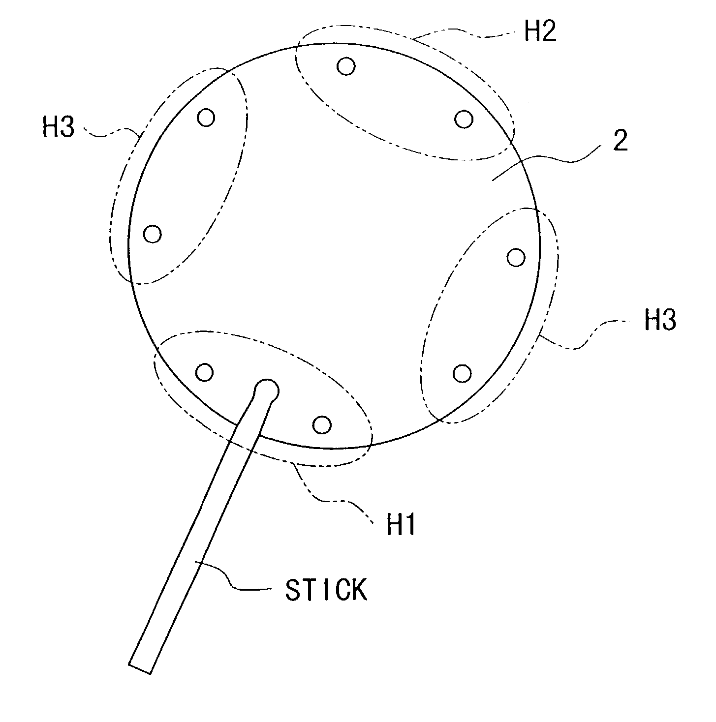
[0088]FIG. 12 is a plan view showing an appearance of a musical tone control apparatus of a percussion instrument type such as an electronic drum device, which is designed in accordance with embodiment 3 of the invention.

[0089]The musical tone control apparatus of FIG. 12 has an upper case 210. On a panel of the upper case 210, there are provided four big pad units 220 each having a big pad skin portion to be beaten as well as three small pad units 220′ each having a small pad skin portion to be beaten. Sound grooves “230” (of speaker covers) of speakers (not shown) are formed at left and right areas on the panel of the upper case 210. Thus, the apparatus is capable of producing stereophonic sounds. In addition, an operation panel 240 containing switches, dial controls and indicators is arranged at a base end portion of the upper case 210 by which a performer stands. Further, an hollow portion 250 (surrounded by a dotted line) is formed under the upper cover 210 to p...


PUM


Abstract

A sensing device is constructed by a sensor case which is attached to a bottom surface of a footwear (e.g., sole of a shoe) and which contains a piezoelectric sensor, a sensor fixing member, a disc plate pressure member and an annular elastic member. The sensor fixing member has elastic deformability so that the sensor fixing member is located to face with the disc plate pressure member with an air gap in which the sensor fixing member is capable of deforming within a limit of elasticity thereof. Thus, it is possible to perform musical tone control in response to an output of the piezoelectric sensor when a foot motion is applied to the footwear. In addition, a musical tone control apparatus of a percussion instrument type is constructed using a pad unit stored in a pad storage portion of an upper case. Herein, the pad unit is constructed by a pad skin unit and a sensing unit. The pad skin unit has a beat surface to be beaten, while the sensing unit contains a piezoelectric sensor, a sensor fixing member and a radial pressure member. Both of the sensor fixing member and the disc plate pressure member (or radial pressure member) are assembled together in such a way that center parts thereof are securely fixed to each other, so the piezoelectric sensor is capable of producing a same output in response to same external force (e.g., foot step force or beat force), regardless of directions to apply such force.

Description

[0001]This is a continuation of U.S. patent application Ser. No. 09 / 812,295, filed Mar. 20, 2001, now U.S. Pat. No. 6,639,140, which is a divisional of U.S. patent application Ser. No. 09 / 281,488 filed Mar. 30, 1999, now U.S. Pat. No. 6,326,539.BACKGROUND OF THE INVENTION[0002]1. Field of the Invention[0003]This invention relates to musical tone control apparatuses using piezoelectric sensors and sensing devices having pressure sensibility used for electronic musical instruments.[0004]This application is based on Patent Application No. Hei 10-184437 and Patent Application No. Hei 10-217146 both filed in Japan, the contents of which are incorporated herein by reference.[0005]2. Description of the Related Art[0006]Conventionally, there are provided a variety of technologies for musical tone controls using pressure sensitivity. For example, the paper of U.S. Pat. No. 4,043,241 (which corresponds to Japanese Patent Publication No. Sho 54-19338) discloses a musical shoe, i.e., a shoe-typ...

Claims


Application Information

Patent Timeline
Patent Type & Authority Patents(United States)
IPC IPC(8): G10H3/00G10H3/14
CPCG10H3/14G10H3/146Y10S84/24G10H2220/525G10H2220/336
Inventor MISHIMA, JUNICHI
Owner YAMAHA CORP
Why Eureka
Try Eureka