I/Q distortion compensation for the reception of OFDM signals

Active Publication Date: 2006-03-28
CIENA
View PDF19 Cites 109 Cited by
  • Summary
  • Abstract
  • Description
  • Claims
  • Application Information

AI Technical Summary

Problems solved by technology

The distortion on the communication channel is caused by factors such as inter-symbol interference, delay spread, frequency selective fading, narrowband interference, co-channel interference, and adjacent channel interference.
The non-identical amplitude and phase responses in the I and Q paths in the modulator and the demodulator, and the non-linear phase characteristics in the low pass filters in each of the I and Q branches in the modulator and the demodulator may be caused by inaccuracies in analog components used in the modulator and the demodulator.
Ho

Method used


Image

  • I/Q distortion compensation for the reception of OFDM signals
  • I/Q distortion compensation for the reception of OFDM signals
  • I/Q distortion compensation for the reception of OFDM signals

Examples


Embodiment Construction

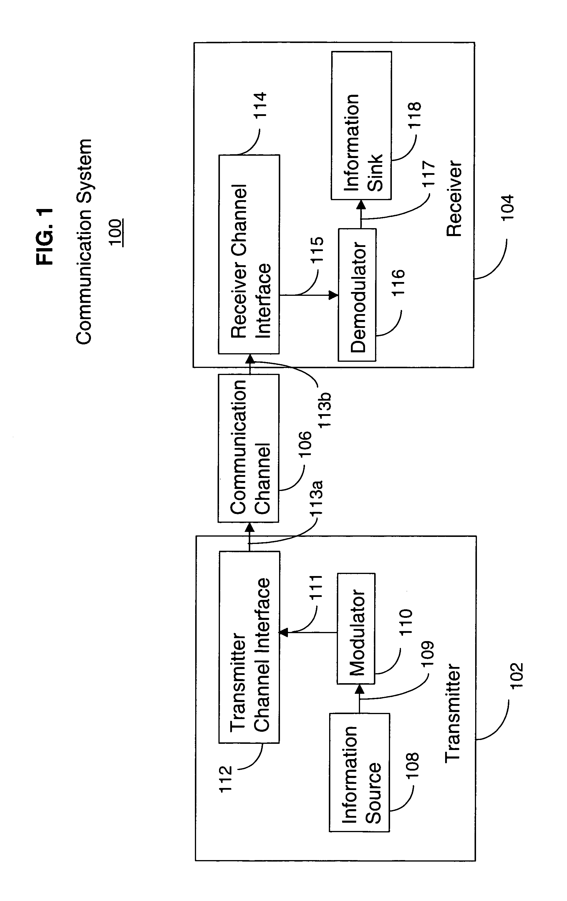
[0025]FIG. 1 illustrates a block diagram of a communication system 100, including a transmitter 102, a receiver 104, and a communication channel 106, in accordance with the preferred embodiments of the present invention. The transmitter 102 generally includes an information source 108, a modulator 110, and a transmitter channel interface 112. The receiver generally includes a receiver channel interface 114, a demodulator 116, and an information sink 118.

[0026]In the transmitter 102, the information source 108 is electrically coupled to the modulator 110 and adapted to generate a transmit signal stream 109 responsive to receiving an input signal (not shown), which may be generated by an electronic circuit or by a human. The modulator 110 is electrically coupled to the transmitter channel interface 112 and adapted to generate a modulated signal 111 responsive to receiving the transmit signal stream 109. The transmitter channel interface 112 is electrically coupled to the communication...


PUM


Abstract

A transmitter (102) generates a first set of data symbols and a first pilot symbol (601) at a first time, and a second set of data symbols and a second pilot symbol (602) at a different, second time. The first (601) and second (602) pilot symbols are each represented by first (701) and second (702) pilot carriers, respectively, located at first (703) and second (704) predetermined sample frequencies, respectively, in a channel bandwidth. For the first pilot symbol (601), the first (701) and second (702) pilot carriers have first and second predetermined values, respectively. For the second pilot symbol (602), the first (701) and second (702) pilot carriers have third and fourth predetermined values, respectively. A receiver (104) measures the first, second, fourth and third predetermined values responsive to receiving the first (601) and second (602) pilot symbols to determine first, second, third and fourth estimates of channel distortion, respectively, for compensating and recovering the first and the second sets of data symbols.

Description

FIELD OF THE INVENTION[0001]The present invention relates generally to communication systems, and more particularly to in-phase (I) / quadrature-phase (Q) distortion compensation for the reception of orthogonal frequency division multiplex (OFDM) signals.BACKGROUND OF THE INVENTION[0002]A communication system, such as radiotelephone system, generally includes a transmitter communicating with a receiver over a communication channel. Characteristics of well-designed communication systems include being inexpensive, simple, small, easy to manufacture, and power efficient, while meeting performance specifications and customer expectations.[0003]Communication systems may communicate signals using single or multiple carrier modulation, depending on the particular application. One type of multiple carrier modulation (MCM) is orthogonal frequency division multiplex (OFDM). OFDM is a modulation method that transmits a data stream in parallel using many orthogonal sub-carriers to transmit a sign...

Claims


Application Information

Patent Timeline
IPC IPC(8): H04L7/00
CPCH04L5/0048H04L25/0226H04L27/364H04L27/3863H04L27/2613H04L5/0007H04L25/0228H04L2027/0016H04L27/2655H04L27/26134
Inventor KIRKLAND, WILLIAM R.
Owner CIENA
Why Eureka
Try Eureka