
Mobile communication system, base station control device and radio base station forming the same, and communication timing control method thereof

a mobile communication system and control device technology, applied in the field of mobile communication system, base station control device and radio base station forming the same, can solve the problems of increasing the total amount of delay of the entire system, reducing unable to have an intention to suppress the increase in the so as to reduce the load and scale of the base station control device to be suppressed, reduce the effect of data buffering time and increase in the load

Inactive Publication Date: 2006-03-28
NEC CORP
View PDF9 Cites 7 Cited by
  • Summary
  • Abstract
  • Description
  • Claims
  • Application Information

AI Technical Summary

Benefits of technology

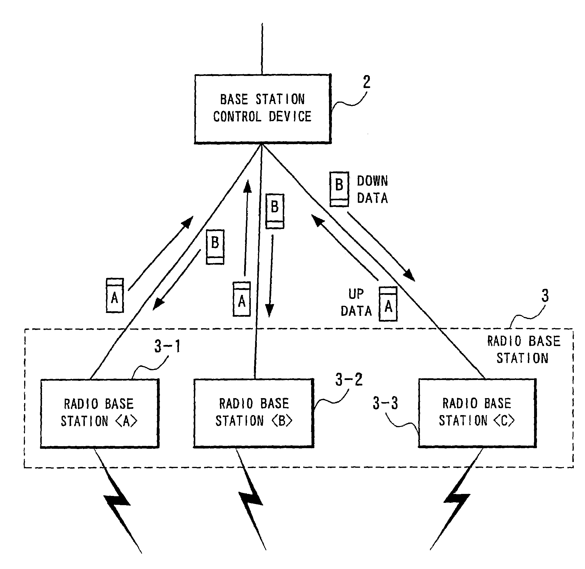
[0026]Accordingly, an object of the present invention is to provide a mobile communication system, a base station control device and a radio base station forming the system, and a communication timing control method in the system which enable an increase in load and scale of the base station control device to be suppressed, as well as enabling reduction in a user data transmission time in the system as a whole by reducing a data buffering time in the base station control device.

Problems solved by technology

With this timing control method, when the amount of transmission delay is small, the base station control device 2 needs to buffer user data for a time period approximate to a total delay time in RAN, which might invite an increase in the total amount of delay of the entire system.
In addition, since timing control between the radio base station and the base station control device is complicated to make it difficult to reduce a delay time of user data transmission in the system as a whole.
These techniques, however, fail to have an intention to suppress an increase in the scale of the base station control device, while reducing a user data transmission time in the system as a whole by reducing a user data (frame) buffering time in the base station control device.

Method used


Image

  • Mobile communication system, base station control device and radio base station forming the same, and communication timing control method thereof
  • Mobile communication system, base station control device and radio base station forming the same, and communication timing control method thereof
  • Mobile communication system, base station control device and radio base station forming the same, and communication timing control method thereof

Examples


Embodiment Construction

[0069]The preferred embodiment of the present invention will be discussed hereinafter in detail with reference to the accompanying drawings. In the following description, numerous specific details are set forth in order to provide a thorough understanding of the present invention. It will be obvious, however, to those skilled in the art that the present invention may be practiced without these specific details. In other instance, well-known structures are not shown in detail in order to unnecessary obscure the present invention.

[0070]In the following, detailed description will be made of a preferred mode of implementation of a mobile communication system, a base station control device and a radio base station forming the system, and a communication timing control method in the system according to the present invention.

[0071]FIG. 3 is a timing chart showing a timing control method at the time of communication start according to the present invention.

[0072]The base station control dev...


PUM


Abstract

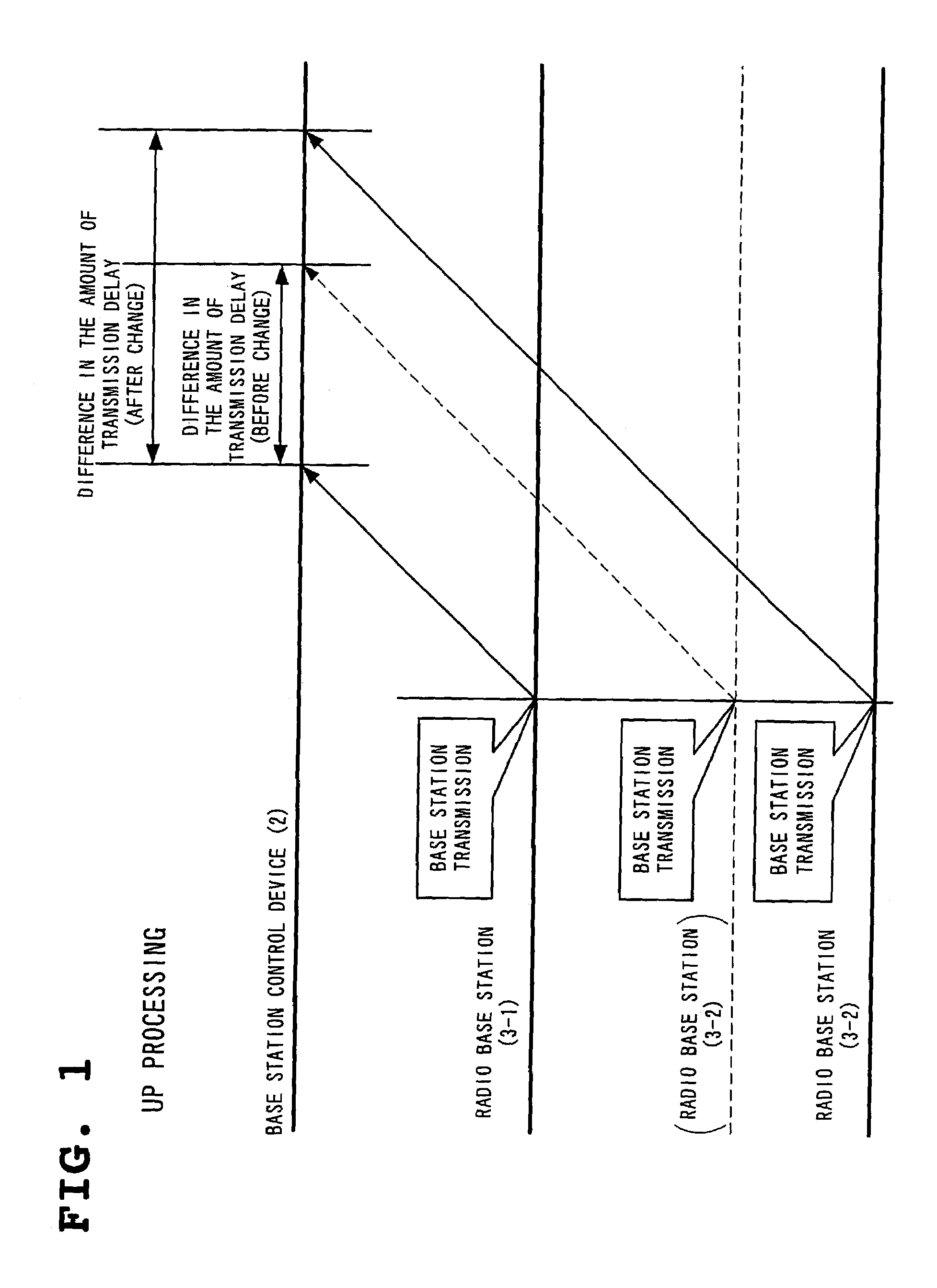
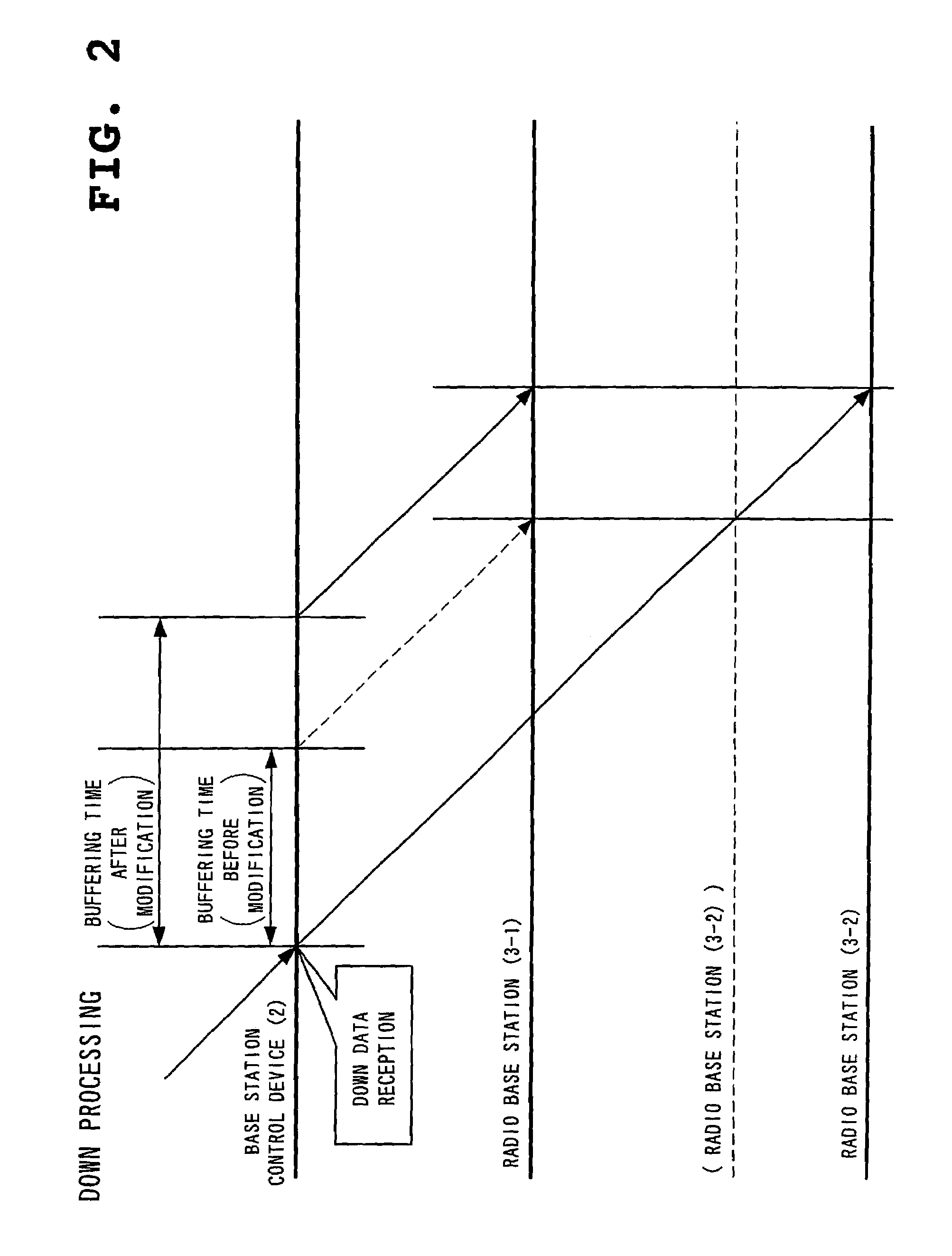
Among a plurality of radio base stations, to a radio base station whose transmission delay time between a base station control device and its own station will be the longest, down data from the base station control device is transmitted to have a buffering time of zero, while to the other radio base stations, data is transmitted with a buffering time corresponding to the degree of relative shortness of a transmission delay time applied, and the buffering time is modified by monitoring a change of a difference in delay time of up data from the radio base station.

Description

BACKGROUND OF THE INVENTION[0001]1. Field of the Invention[0002]The present invention relates to a mobile communication system such as a cellular phone, a base station control device and a radio base station forming the system, and a communication timing control method in the system.[0003]2. Description of the Related Art[0004]Mobile communication system whose representative is a cellular phone or a PHS is an information communication means indispensable in the information age of today. The mobile communication is realized by transmission and reception of radio signals by a mobile terminal to and from a radio base station and transmission and reception of wire signals by the radio base station to and from a network connecting to a communication target. Since one radio base station has its communicable area limited, a plurality of radio base stations form an area (cell) covering communication to compensate for each other, thereby enabling mobile communication everywhere. In a case wh...

Claims


Application Information

Patent Timeline
Patent Type & Authority Patents(United States)
IPC IPC(8): H04B1/38H04M1/00H04B7/26H04B17/309H04W24/06H04W28/14H04W36/08H04W36/38H04W56/00H04W88/12H04W92/00H04W92/12
CPCH04W56/002H04W92/045
Inventor KOBAYASHI, KAZUNARI
Owner NEC CORP
Learn More