Device for fastening screw onto workpiece and method of judging loosening of screw

a screw and screw technology, applied in the direction of process control, machine control, process control, etc., can solve the problems of difficult to judge screw loosening dimension error, and screw loosening that occurs within the allowable error range, so as to improve the rate of correct judgment and increase work load and operation time

Active Publication Date: 2016-06-21
DENSO WAVE INC
View PDF8 Cites 8 Cited by
  • Summary
  • Abstract
  • Description
  • Claims
  • Application Information

AI Technical Summary

Benefits of technology

[0012]Thus it is desired to provide a screw fastening device and a screw loosening judging method capable of improving the rate of correct judgment in judgment of screw loosening, without causing increase in work load and operation time.
[0016]Therefore, a screw loosening judging section judges screw loosening based on the first bit position and the second bit position. In other words, the screw loosening judging section judges screw loosening based on a bit position measured in a state in which the screw is seated before the screw is fastened and a bit position measured in a state in which the screw is seated after the screw has been fastened. At this time, as described above, the first bit position is measured separately for each screw. In addition, the screw of which the first bit position has been measured is directly fastened onto the workpiece. In other words, the first bit position and the second bit position serving as reference values for judging screw loosening are measured for each screw and each workpiece. As a result, judgment of screw loosening can be performed while absorbing allowable error of the screw and individual differences of the workpieces, without using the dimensions of specific areas of the screw as reference. Therefore, the reference values are not limited by the allowable error of the screw, the individual differences of the workpieces, and the like. The rate of correct judgment in judgment of screw loosening can be improved.
[0017]Furthermore, as described above, the first bit position and the second bit position are measured for each screw and each workpiece. Therefore, a common reference range taking into consideration the allowable error of the screw and the individual differences of workpieces is no longer required to be provided. In other words, the operation itself for data measurement for setting a common reference value is no longer required. Therefore, work load and operation time required for judgment of screw loosening can be reduced.

Problems solved by technology

In contrast, the “screw lock” means that a screw is locked and cannot be screwed into the screw hole any more during its screw fastening operation due to irregularities in sizes of threads, oblique insertion of the screw into a screw hole, packed dusts, or others.
However, the dimensions have allowable error.
However, when judgment of screw loosening is performed with reference to the height of the head section of the screw as described above, screw loosening may not be correctly judged.
This problem may occur even when the dimension of another area, such as the length of the shaft section of the screw, serves as reference.
Therefore, screw loosening that occurs within the range of allowable error is difficult to judge.
In other words, in the conventional judgment of screw loosening, the reference range is limited by the allowable error of the screw.
Therefore, improving judgment accuracy, or in other words, improving the rate of correct judgment to be a constant value or more is difficult.
Therefore, similar problems occur even when the reference range is set based on standard values of the dimensions of the workpiece.
Regardless of the increase in work load and operation time, improving the rate of correct judgment in the judgment of screw loosening is difficult, as described above.
Therefore, even when the allowable error differs for each screw, erroneous judgment caused by judgment of screw loosening being affected by allowable error is considered not to occur.

Method used


Image

  • Device for fastening screw onto workpiece and method of judging loosening of screw
  • Device for fastening screw onto workpiece and method of judging loosening of screw
  • Device for fastening screw onto workpiece and method of judging loosening of screw

Examples


Embodiment Construction

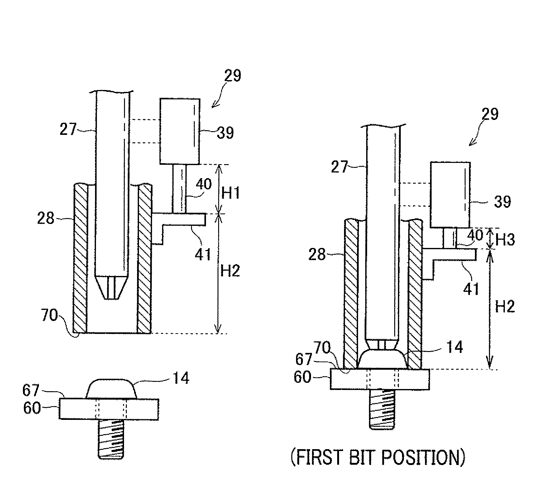
[0029]An embodiment of a screw fastening device and a screw loosening judging method will hereinafter be described with reference to FIG. 1 to FIG. 8A-FIG. 8D.

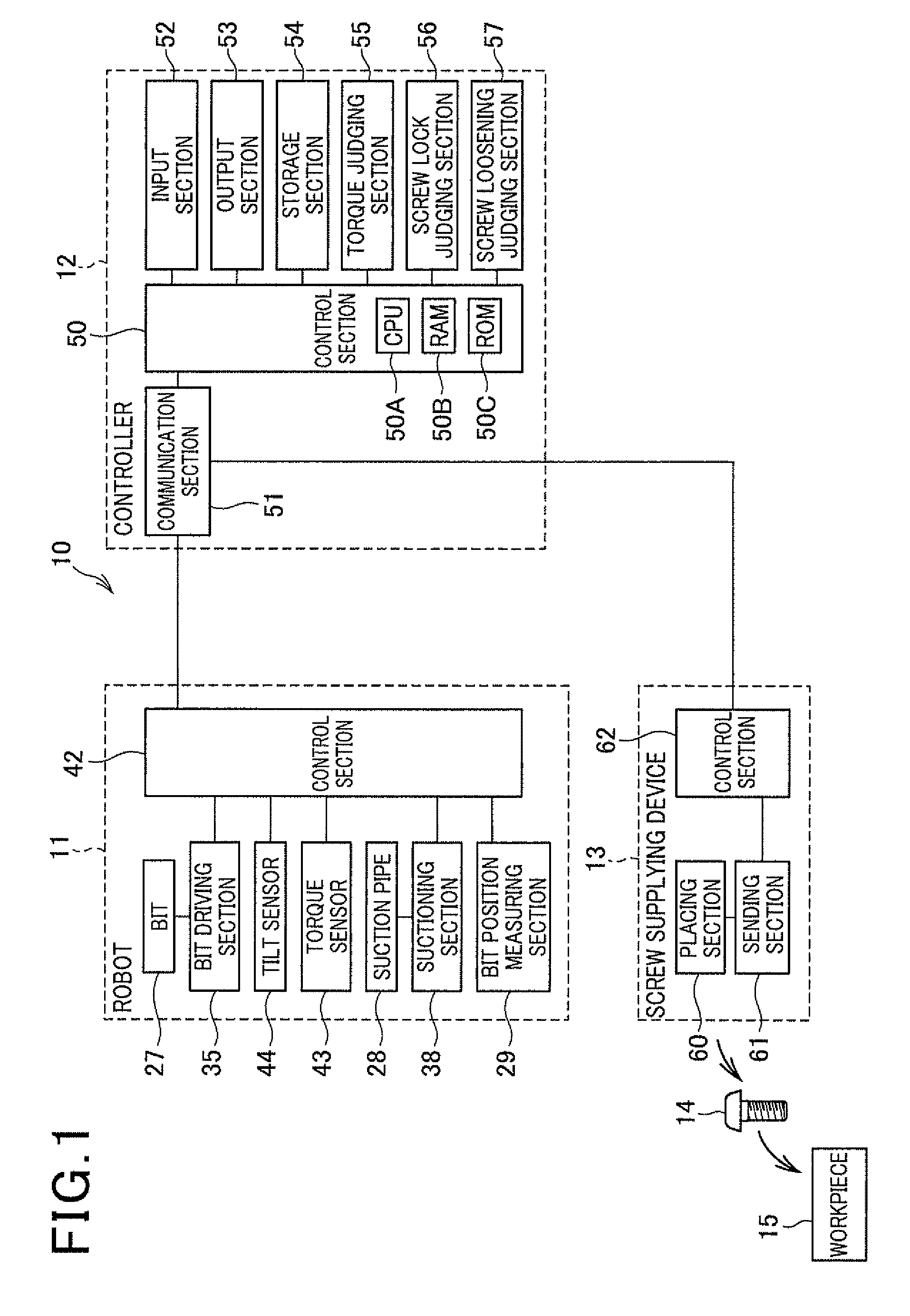
[0030]A screw fastening device 10 according to the present embodiment includes a robot 11 and a controller 12, as shown in FIG. 1, The screw fastening device 10 acquires a screw 14 supplied from a screw supplying device 13. The screw fastening device 10 then fastens the acquired screw 14 onto a workpiece 15 serving as a subject.

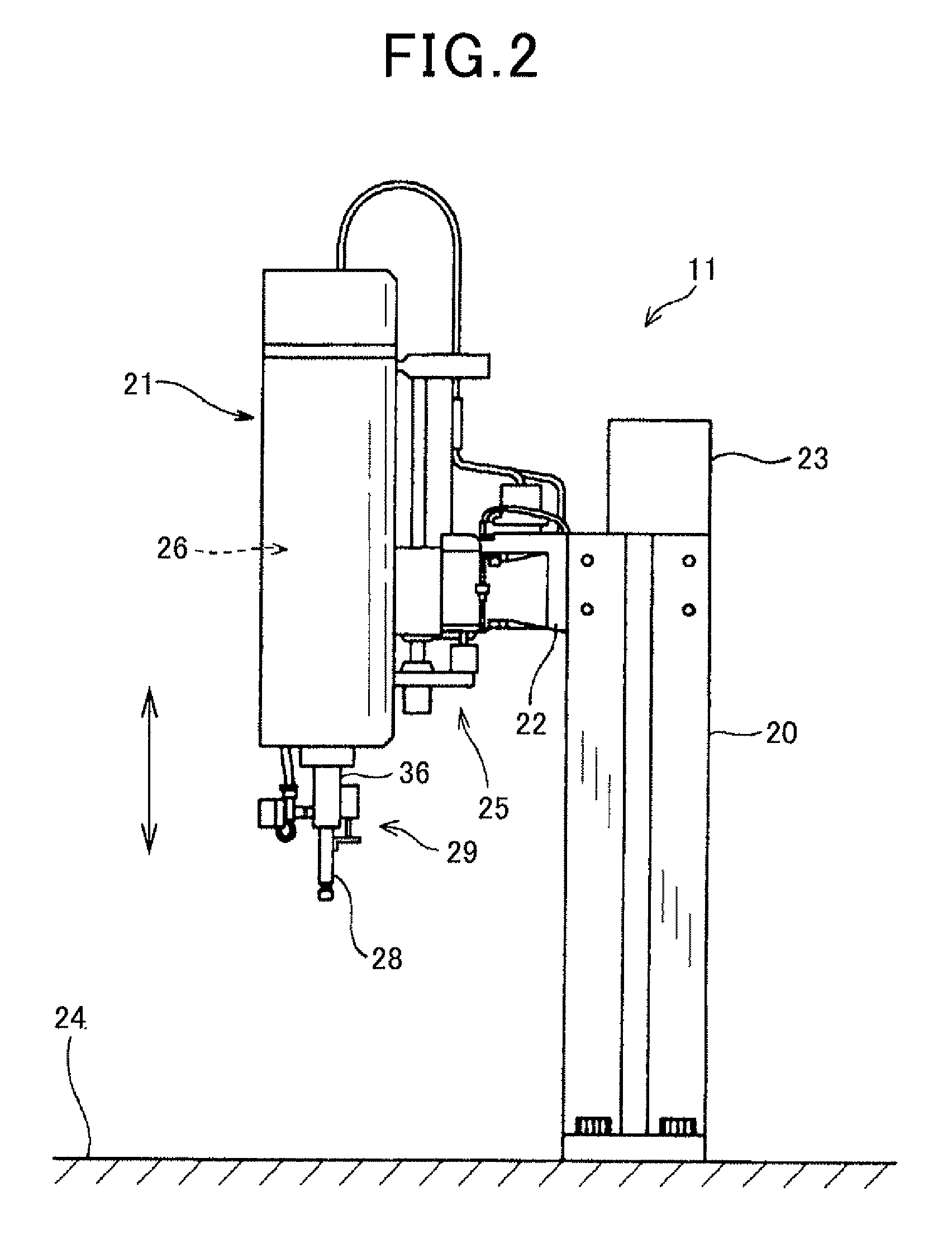
[0031]The robot 11 of the screw fastening device 10 includes a base section 20, a head section 21, an arm section 22, and a connector box 23, as shown in FIG. 2 and FIG. 3. The base section 20 is fixed to a mounting surface 24 on which the robot 11 is mounted. The head section 21 is connected to the base section 20 by the arm section 22. The arm section 22 is attached to an upper end side of the base section 20. The head section 21 is provided such as to be rotatable in relation to the base section 20. ...


PUM

PropertyMeasurementUnit
torqueaaaaaaaaaa
sizesaaaaaaaaaa
heightaaaaaaaaaa

Abstract

In judging loosening of a crew, a measuring section measures a position of a bit as a relative position in relation to a placement surface of a screw supplying device when the screw is acquired from the screw supplying device. The measuring section also measures the position of the bit as a relative position in relation to a workpiece surface when fastening of the screw onto a workpiece has been completed. A judging section judges that screw loosening has not occurred when, based on the first and second bit positions, a difference between the first and second bit positions falls within an allowable range. The judging section judges that screw loosening has occurred when the difference does not fall within the allowable range.

Description

CROSS-REFERENCE TO RELATED APPLICATION[0001]This application is based on and claims the benefit of priority from earlier Japanese Patent Application No. 2011-198225 filed Sep. 12, 2011, the description of which is incorporated herein by reference.BACKGROUND OF THE INVENTION[0002]1. Field of the Invention[0003]The present invention relates to a screw fastening device and a method of judging loosening of screws.[0004]2. Description of the Related Art[0005]A screw fastening device has been known since the past that acquires a screw from a screw supplying device and fastens the acquired screw onto a workpiece serving as a subject.[0006]A screw fastening device such as this performs screw fastening torque control, detection of screw angle and screw lock, and the like when fastening a screw. Reduction in screw fastening failure is achieved through these control and detection operations. In addition, the screw fastening device judges whether or not the screw is tightly seated on the workpi...

Claims


Application Information

Patent Timeline
Patent Type & Authority Patents(United States)
IPC IPC(8): B23P19/06B25J9/16
CPCB23P19/06B23P19/066B25J9/1679G05B2219/45091Y10T29/49764
Inventor HARADA, TOYOO
Owner DENSO WAVE INC
Why Eureka
Try Eureka