High accuracy vapor generation and delivery for thin film deposition

a thin film, high-accuracy technology, applied in chemical vapor deposition coatings, coatings, metallic material coating processes, etc., can solve the problems of inability to achieve high-accuracy vapor generation, low vapor delivery rates in milligram, microgram and nanogram per second ranges, and achieve the effect of low vapor delivery rates

Inactive Publication Date: 2006-07-06
MSP
View PDF12 Cites 23 Cited by
  • Summary
  • Abstract
  • Description
  • Claims
  • Application Information

AI Technical Summary

Benefits of technology

[0011] The present invention involves injecting a liquid and gas into a vapor holding chamber held at a sufficiently high temperature to insure all the liquid injected is vaporized and held in the chamber as a vapor. The gas / vapor mixture is then delivered to a second chamber maintained at a lower pressure for subsequent delivery to the deposition chamber in which the deposition substrate, i.e. the wafer, is held.
[0012] The two chambers described above are referred to respectively as the source chamber and the delivery chamber. Both chambers are preferably equipped with a pressure sensor to monitor the pressure of the gas / vapor mixture in the chamber. Both chambers are equipped with inlet and exit gas and liquid shut-off valves. When the pressure in the delivery chamber falls below a certain preset threshold due to vapor delivery to the deposition chamber, the valve between the source and delivery chambers is opened. This allows the gas / vapor mixture from the source chamber to flow into the delivery chamber, thereby restoring the delivery chamber to its proper operating pressure conditions. As the gas / vapor mixture flows into the delivery chamber, the source chamber pressure drops. When the pressure falls below a certain pre-set threshold, the required amount of gas and liquid is injected into the source chamber to restore the chamber pressure to the pre-set value. By this means, both the source and delivery chambers are controlled to within certain pressure limits, thereby insuring the constant vapor delivery at a precise rate. The method of approach can lead to extremely low vapor delivery rates in the milligram, microgram and nanogram per second ranges that are not possible by other vapor delivery methods.
[0013] Another aspect of the present invention includes an apparatus having a single source chamber for containing a gas and a vaporized deposition component and with the source chamber being maintained at a temperature higher than the saturation temperature of the deposition component for the pressure being generated. The apparatus further includes a deposition chamber for receiving the gas and vaporized deposition component directly from the source chamber with the deposition chamber being at a pressure less than the pressure in the source chamber. A method using this apparatus includes forming the gas vapor mixture having the deposition component in the source or holding chamber and then delivering the gas vapor mixture from the holding chamber to a deposition chamber via the pressure difference between the holding chamber and the deposition chamber.
[0014] For ALD applications, the delivery chamber is usually sized to have a specific volume so that the required amount of gas and vapor mixture is held in the delivery chamber prior to gas / vapor delivery. The entire content of the delivery chamber is then delivered to the deposition chamber by opening the valve between the delivery and deposition chambers to deliver a precise dose of vapor along with a fixed amount carrier gas into the deposition chamber.

Problems solved by technology

The method of approach can lead to extremely low vapor delivery rates in the milligram, microgram and nanogram per second ranges that are not possible by other vapor delivery methods.

Method used


Image

  • High accuracy vapor generation and delivery for thin film deposition
  • High accuracy vapor generation and delivery for thin film deposition
  • High accuracy vapor generation and delivery for thin film deposition

Examples


Embodiment Construction

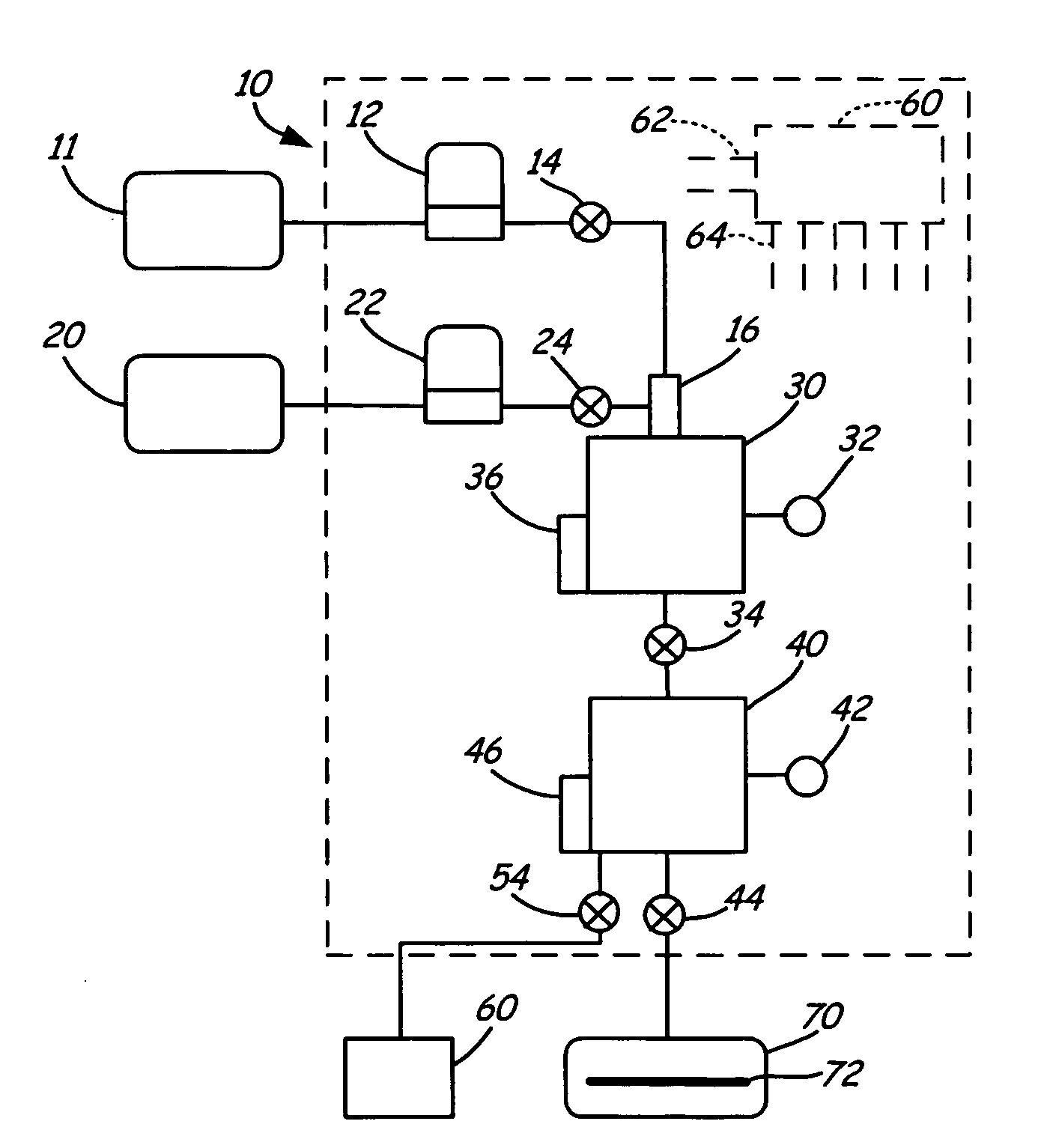
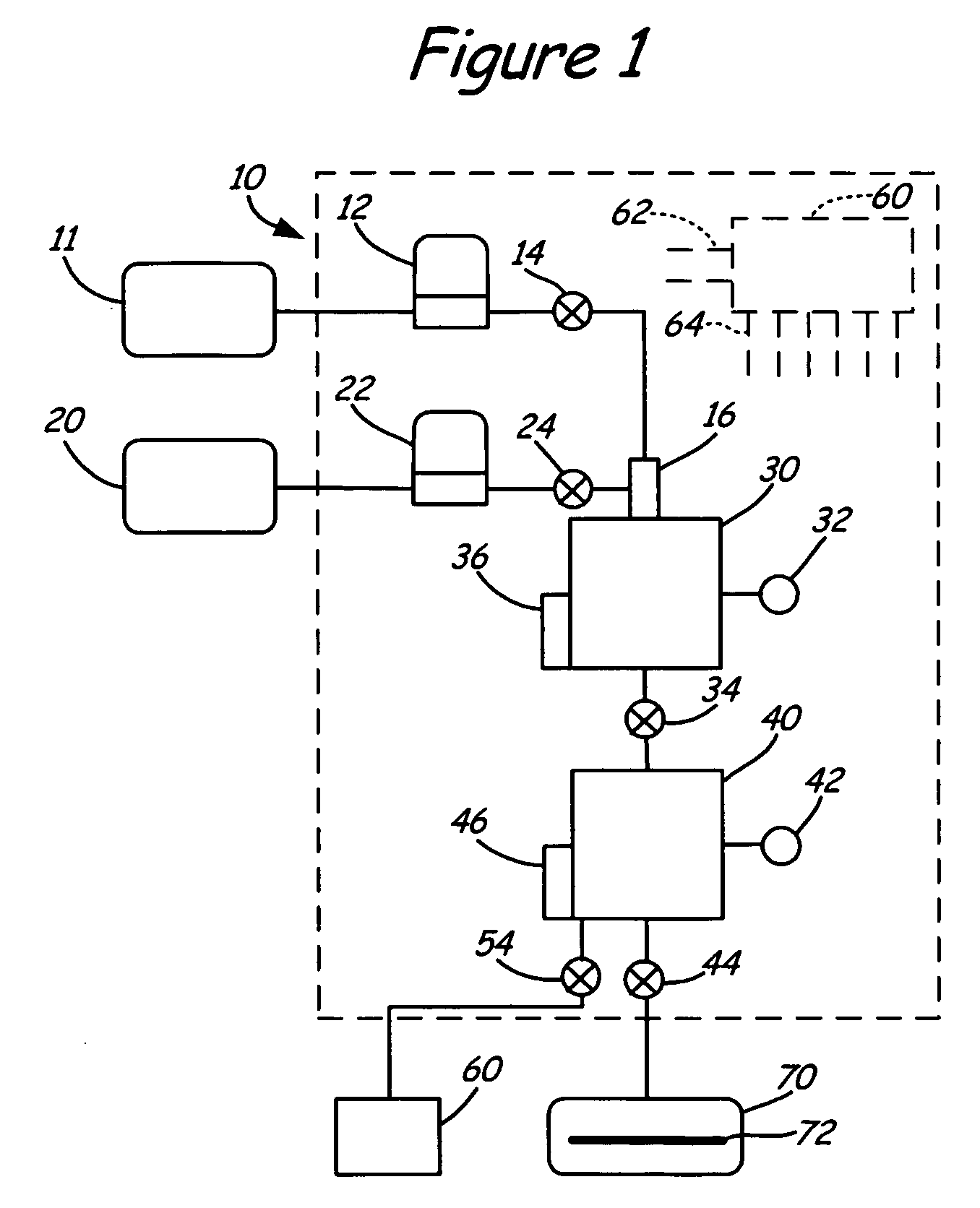
[0017]FIG. 1 shows the preferred embodiment of the vaporizing apparatus. The vapor generation and delivery apparatus is shown generally at 10. A reservoir 20 which may be external to the system or be part of the system, contains a liquid under pressure. It provides a source of liquid (deposition component) for use in vaporization. A gas source 11 is also provided and may be external to the system. The reservoir 20 is connected to a liquid flow controller (LFC) 22 which is in turn connected to an inlet flow passageway 16 on the vaporization chamber 30 through the valve 24. The inlet flow passageway 16 provides a passageway for the liquid and gas to flow into the vaporization chamber, 30 from their respective liquid and gas sources. The gas source 11 is connected to a gas flow controller (GFC) 12 and valve 14 to a gas inlet on the inlet flow passageway 16 on the vaporization chamber 30.

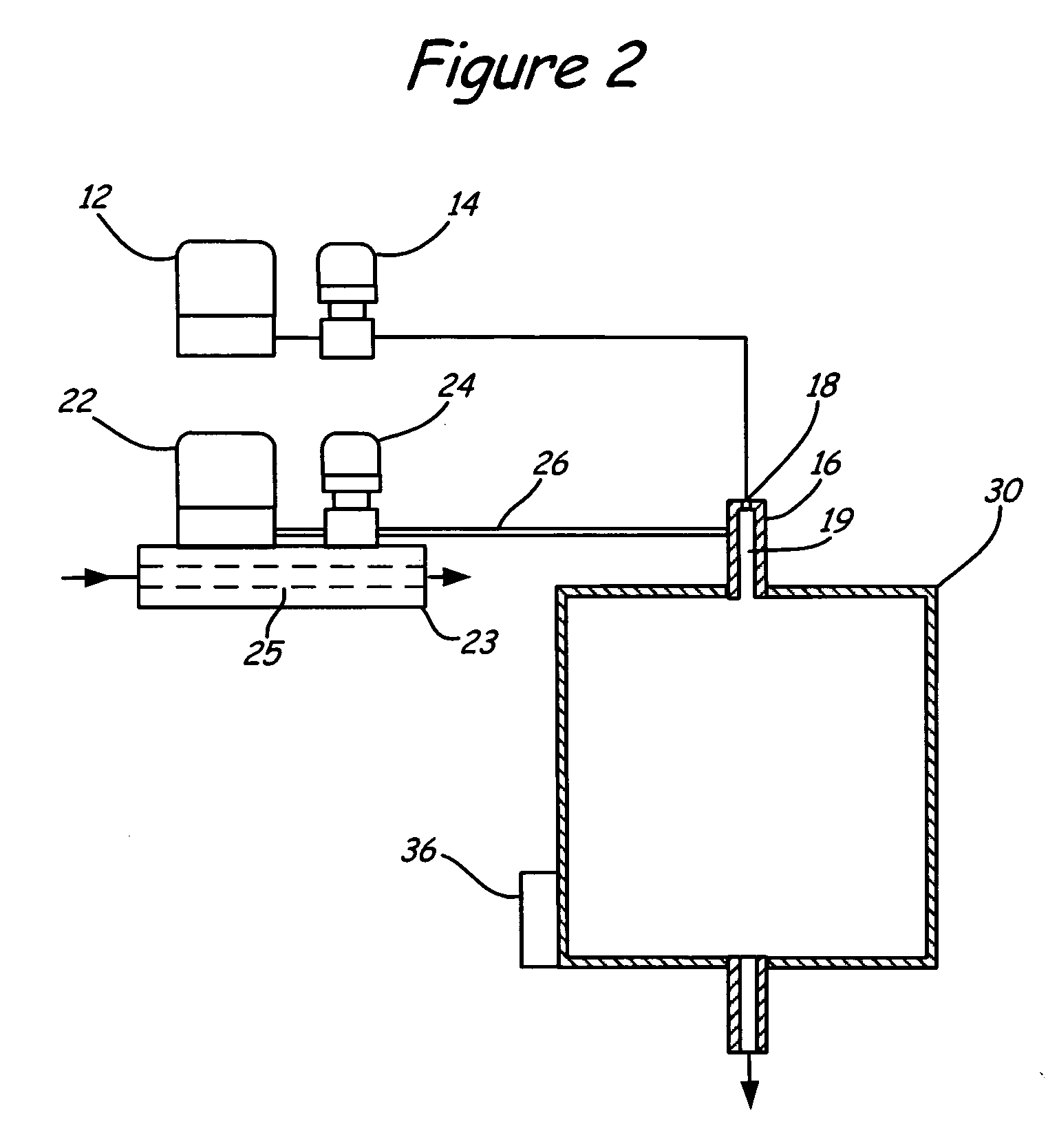
[0018]FIG. 2 shows the manner in which gas and liquid are injected into the vaporization chamber 30...


PUM

PropertyMeasurementUnit
diameteraaaaaaaaaa
thicknessaaaaaaaaaa
diametersaaaaaaaaaa

Abstract

The present invention involves injecting a liquid and gas into a vapor holding chamber held at a sufficiently high temperature to insure all the liquid injected is vaporized and held in the chamber as a vapor. The gas/vapor mixture is then delivered to the deposition chamber in which the deposition substrate is held.

Description

CROSS-REFERENCE TO RELATED APPLICATION [0001] The present application is based on and claims the benefit of U.S. provisional patent application Ser. No. 60 / 640,746, filed Dec. 30, 2004, the content of which is hereby incorporated by reference in its entirety.FIELD OF THE INVENTION [0002] This invention relates to methods and apparatus for thin film deposition for semiconductor device fabrication and related applications. Specifically, it involves thin film deposition with liquid precursor chemicals that must be vaporized prior to film deposition. The method and apparatus described involve direct liquid injection into a heated chamber to generate vapor for delivery to the deposition chamber for film formation. The method and apparatus are particularly useful for those applications where the rate of vapor delivery is small and for which the method that is presently in use is unsatisfactory. BACKGROUND OF THE INVENTION [0003] Thin film formation by chemical vapor deposition (CVD) is a ...

Claims


Application Information

Patent Timeline
Patent Type & Authority Applications(United States)
IPC IPC(8): C23C16/00H01L21/31
CPCC23C16/4481C23C16/4486C23C16/45502C23C16/45512C23C16/45525C23C16/45582C23C16/45585C23C16/45587C23C16/52
Inventor LIU, BENJAMIN Y.H.MA, YAMIN
Owner MSP
Why Eureka
Try Eureka