Method and hydraulic control system for supplying pressure medium to at least one hydraulic consumer

Inactive Publication Date: 2013-08-06
ROBERT BOSCH GMBH
View PDF46 Cites 10 Cited by
  • Summary
  • Abstract
  • Description
  • Claims
  • Application Information

AI Technical Summary

Benefits of technology

The invention is a control system for hydraulic consumers that improves operational reliability and efficiency. It uses a regeneration mode to rapidly move the consumer by adding the pressure fluid from the return side of the pump to the delivery rate. The pump is set based on a pressure regulation to ensure the consumer remains immobile or slows down. The system also includes a comparison of pump flow rate to pressure fluid requirement to decide when to switch to the normal mode, improving the accuracy of the switching time. The control system can be reduced in complexity by using directional control valves and load lowering valves with a secondary pressure limiting function.

Problems solved by technology

A disadvantage of the regeneration / differential circuit, however, is that due to the restraining of the consumer (effective area corresponds approximately to the piston rod area), the consumer cannot be operated with the maximum output.
If a control system of this kind is used in a mobile piece of equipment such as a backhoe loader, a mini- or compact excavator, or a telehandler, then the available digging power in the regeneration mode is too low due to the restraining of the consumer.
In this case, it is often difficult to determine the correct moment to make the switch, as a result of which the consumer remains too long in the regeneration mode with reduced power or the switch to the normal mode is made prematurely even though it would be advantageous to operate the consumer at a high speed.

Method used


Image

  • Method and hydraulic control system for supplying pressure medium to at least one hydraulic consumer
  • Method and hydraulic control system for supplying pressure medium to at least one hydraulic consumer
  • Method and hydraulic control system for supplying pressure medium to at least one hydraulic consumer

Examples


Embodiment Construction

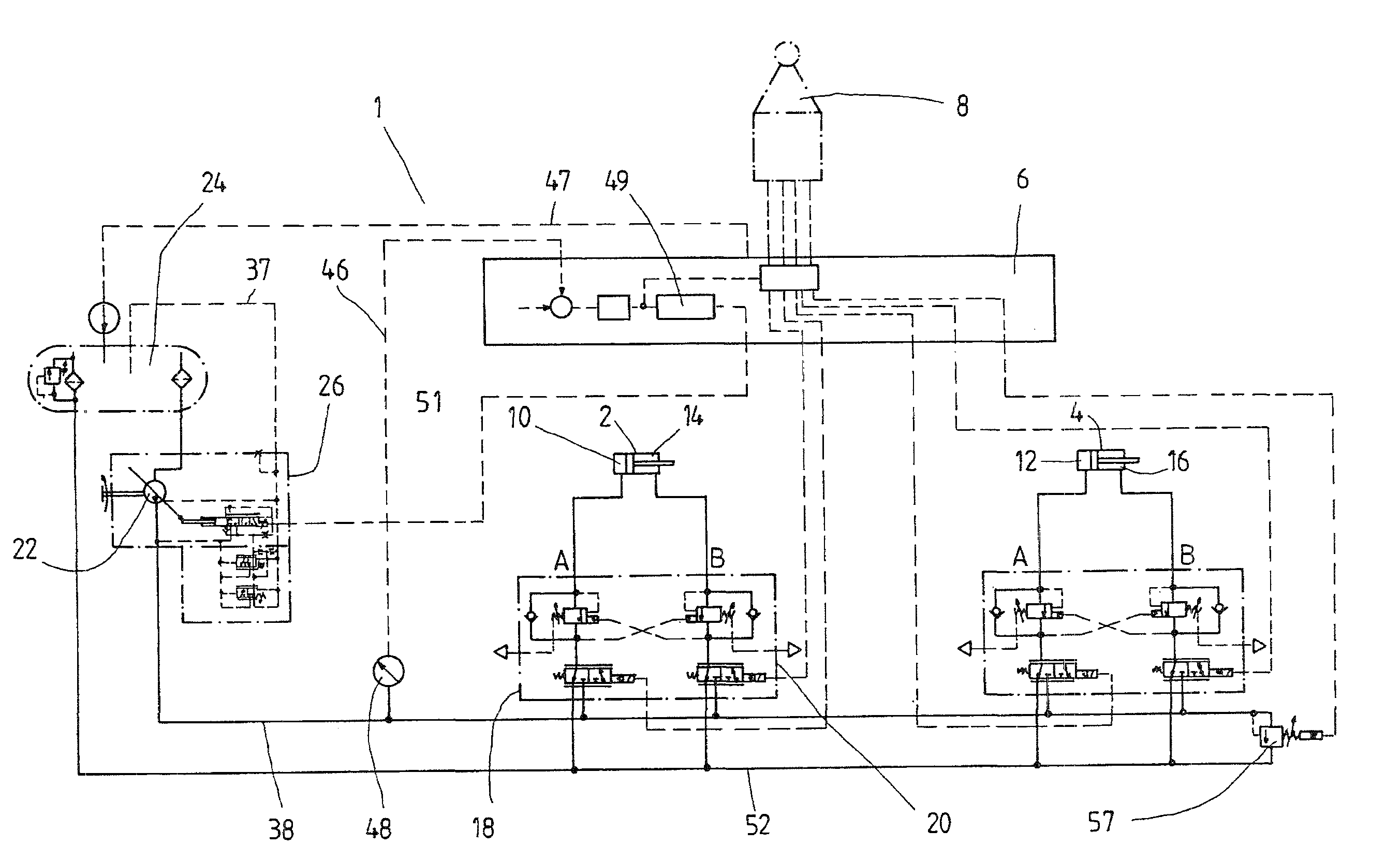
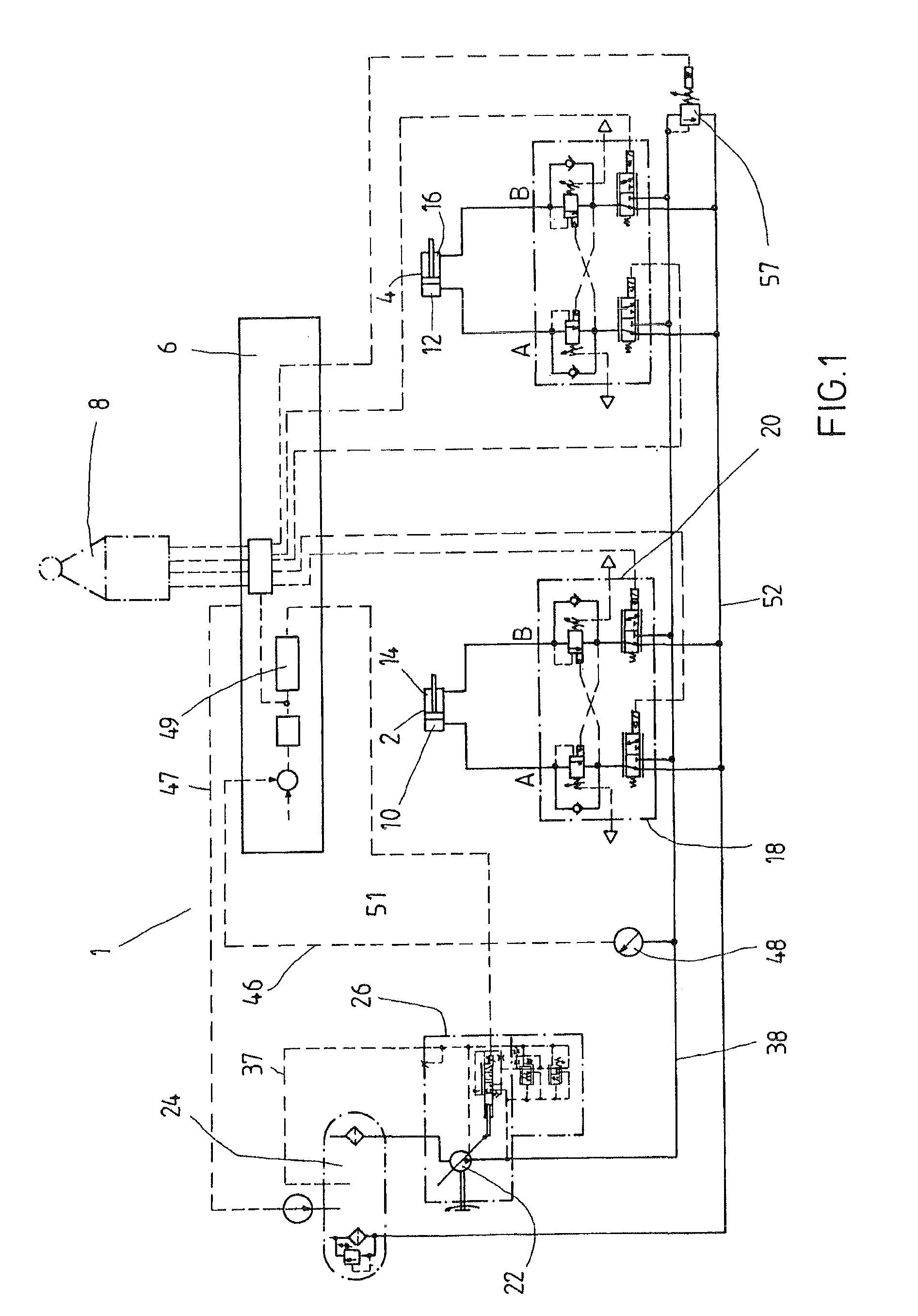
[0026]FIG. 1 shows a hydraulic control system 1 for supplying pressure fluid to two consumers 2, 4 of a piece of mobile equipment such as an excavator, a backhoe loader, a mini- or compact excavator, or a telehandler. It is a so-called

[0027]EFM system (electronic flow management) in which the valve elements that determine the volumetric flow of pressure fluid and the flow direction of the pressure fluid are electrically or electrohydraulically triggered as a function of characteristic curve families stored in a control unit 6. In this case, the setpoint values are input by means of a joystick 8 that is actuated by the operator in order to control the speed and position of the machine components (e.g. booms, shovels) of the piece of equipment.

[0028]In the exemplary embodiment shown, the two consumers 2, 4 are each embodied in the form of a differential cylinder with a pressure chamber 10 or 12 at the bottom and an annular chamber 14 or 16 around the piston rod. These pressure chamber...


PUM


Abstract

The invention relates to a hydraulic control arrangement and to a method for controlling a hydraulic consumer that comprises a pressure chamber on the input side and on the return side, said pressure chamber being connected to an adjusting pump or a tank via a valve device. The valve device is controlled by means of a control unit via which it can be adjusted in a regeneration mode, in which both pressure chambers are connected to the adjusting pump. According to the invention, the adjusting pump is pressure controlled, whereby in the regeneration mode, it is automatically switched to the normal operation in which the supply side of the pressure chamber is connected to the adjusting pump and the return side of the pressure chamber is connected to the tank when the pumping rate falls below the demand for the pressure medium.

Description

CROSS-REFERENCE[0001]The invention described and claimed hereinbelow is also described in PCT / EP2008 / 004990, filed on Jun. 20, 2008 and DE 10 2007 029 358.7, filed on Jun. 26, 2007. This German Patent Application, whose subject matter is incorporated here by reference, provides the basis for a claim of priority of invention under 35 U.S.C. 119 (a)-(d).BACKGROUND OF THE INVENTION[0002]The invention relates to a method for actuating a hydraulic consumer and a hydraulic control system for supplying pressure medium to the consumer.[0003]U.S. Pat. No. 5,138,883 A has disclosed a hydraulic control system in which a consumer such as a differential cylinder can be supplied via a valve device—which is equipped with two continuously adjustable directional control valves—with pressure fluid that is furnished by a pump. The supply to the consumer and the return from it each contain a respective continuously adjustable directional control valve. In their neutral positions, the directional contro...

Claims


Application Information

Patent Timeline
IPC IPC(8): F15B11/024F15B21/14
CPCF15B11/003F15B11/024F15B11/0445F15B2211/20546F15B2211/3057F15B2211/50545F15B2211/7053F15B2211/5059
Inventor KAUSS, WOLFGANGDESBOIS-RENAUDIN, MATTHIEU
Owner ROBERT BOSCH GMBH
Why Eureka
Try Eureka