Low-cost methods and devices for the decoding of product cases

a low-cost, product-case technology, applied in the field of communication systems, can solve the problems of reducing the information density of the word, reducing the accuracy of the word, so as to achieve the effect of increasing the information density

Inactive Publication Date: 2006-10-10
CANON KK
View PDF13 Cites 23 Cited by
  • Summary
  • Abstract
  • Description
  • Claims
  • Application Information

AI Technical Summary

Benefits of technology

[0046]However, in modern information carriers, it is sought to increase information density. Due to this, when such a carrier is affected by a physical defect such as a scratch, a high number of information symbols may be rendered unreadable. This problem may nevertheless be remedied using very long codewords. This is why it has been sought to construct codes that naturally offer a greater length than the Reed-Solomon codes, and by making up such codes, very long product codes may be constructed.

Problems solved by technology

Even though such decoding methods have certain advantages, they have the drawback of giving rise to a relatively high rate of false corrections.
This is because each time a row or column is erased, any information about the word which could have remained in that row or that column despite the transmission errors which that row or column has undergone, is of course lost.
However, the fact of accepting the “correction” supplied by the algorithms each time they are able to supply a “correction” means that often, when the number of errors in a row or column submitted to the row or column algorithm is relatively high, a new row or column will be entered, which is in fact tainted with errors (without this having been realized), due to the fact that the algorithm was able to propose an apparently corrected word by modifying a relatively small number of symbols, of which at least one was correct.
An increasing number of false symbols will thus be generated during the subsequent steps of “correcting” this word, and in these circumstances, a highly erroneous “associated codeword” will generally result.

Method used


Image

  • Low-cost methods and devices for the decoding of product cases
  • Low-cost methods and devices for the decoding of product cases
  • Low-cost methods and devices for the decoding of product cases

Examples


Embodiment Construction

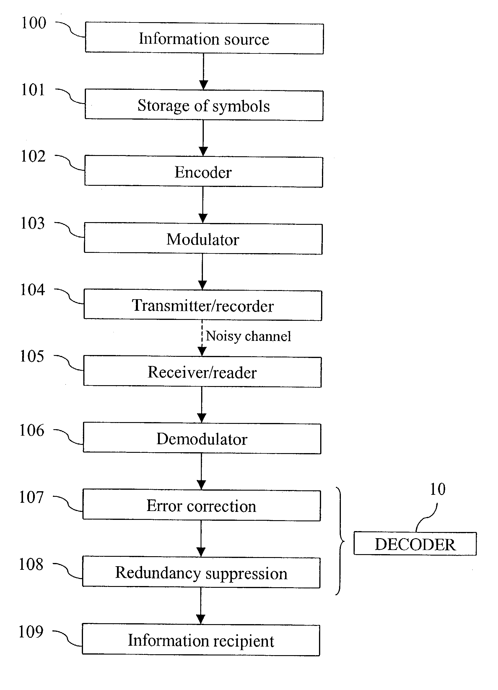
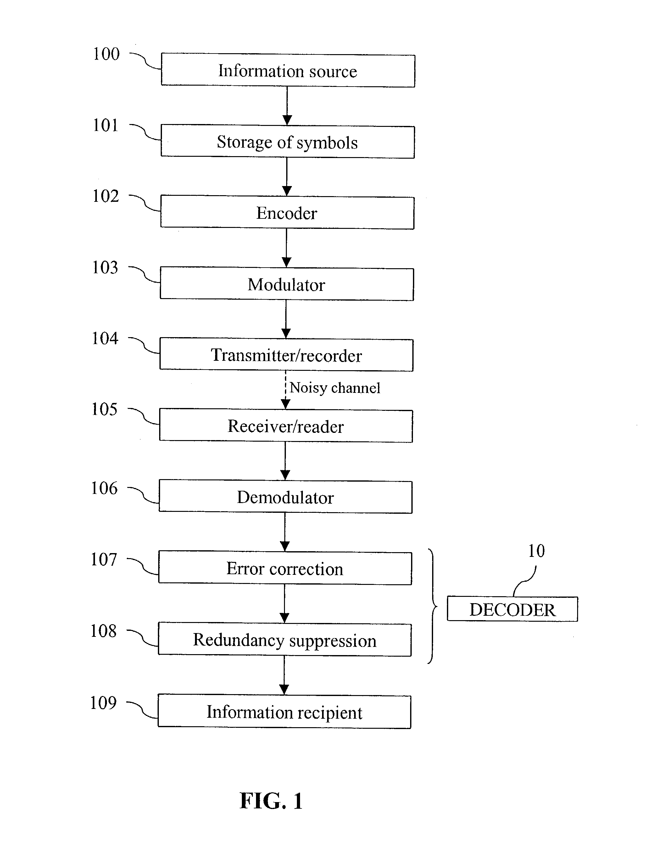
[0072]FIG. 1 is a block diagram of a system for transmitting information using a channel encoding according to the invention.

[0073]The function of this system is to transmit information of any nature from a source 100 to a recipient or user 109. First of all, the source 100 puts this information into the form of symbols belonging to a certain alphabet (for example quadruplets of bits), and transmits these symbols to a storage unit 101, which accumulates the symbols so as to form sets each containing k1·k2 symbols. Next, each of these sets is transmitted by the storage unit 101 to an encoder 102 which adds (n1·n2−k1·k2) redundant symbols to them, so as to build a word of product code in which each row is a word of length n1 belonging to a first component code, and each column is a word of length n2 belonging to a second component code (possibly identical to the first component code).

[0074]The words of product code so formed are next transmitted to a modulator 103, which associates a ...


PUM

PropertyMeasurementUnit
lengthaaaaaaaaaa
sizeaaaaaaaaaa
transmissionaaaaaaaaaa

Abstract

A method of decoding product codes is disclosed, in which the symbols of each codeword may be placed in a table comprising n2 rows and n1 columns, such that the symbols constituting each row form a permitted word of length n1 according to a first component code able to be decoded by means of an algorithm A1 for correction with erasures, and the symbols constituting each column form a permitted word of length n2 according to a second component code able to be decoded by means of an algorithm A2 for correction with erasures. According to the method, a correction of a row or column is only accepted when the result of the correction is deemed reliable, otherwise all the symbols of that row or column are erased. Devices and apparatus adapted to implement this method are also disclosed. The method is preferably applied to algebraic geometric codes.

Description

BACKGROUND OF THE INVENTION[0001]1. Field of the Invention[0002]The present invention concerns communication systems in which, in order to improve the fidelity of the transmission, the data to be transmitted are subjected to a channel encoding. It concerns more particularly a decoding method, as well as the devices and apparatus adapted to implement this method.[0003]2. Description of the Related Art[0004]It will be recalled that so-called “channel” encoding consists, when the “codewords” sent to the receiver are formed, of introducing a certain amount of redundancy in the data to be transmitted. More particularly, by means of each codeword, a predetermined number k of information symbols are transmitted which are chosen from a predetermined “alphabet” of finite size; to these k information symbols are added a number (n−k) of so-called “parity” symbols, taken from the same alphabet, so as to form codewords of length n; the set rules for calculation of the parity symbols as a functio...

Claims


Application Information

Patent Timeline
Patent Type & Authority Patents(United States)
IPC IPC(8): H03M13/00G06F11/10G11B20/18H03M13/15H03M13/29H04L1/00
CPCG11B20/1813H03M13/132H03M13/1515H03M13/29H03M13/2909H03M13/293
Inventor LEHOBEY, FREDERICPIRET, PHILIPPE
Owner CANON KK
Why Eureka
Try Eureka