Dry shaver with a cradle shaving head

a shaving head and cradle technology, applied in the direction of metal working devices, etc., can solve the problems of reducing the angular range of the tilting movement, reducing the ability of the cradle head to follow the contour of the user's skin, and requiring unduly wide dimensions for the hand grip, so as to achieve smooth tilting and depressing movement

Inactive Publication Date: 2006-04-04
MATSUSHITA ELECTRIC WORKS LTD
View PDF13 Cites 32 Cited by
  • Summary
  • Abstract
  • Description
  • Claims
  • Application Information

AI Technical Summary

Benefits of technology

[0015]The hand grip is preferred to have a top guard which projects to overlap the lower end of the cradle head in order to protect the cradle head from moving in directions not associated with the tilt and the depressing movement. In order to add smooth tilting and depressing movement to the cradle head, the top guard is provided with a guide which comes into slidable engagement with a portion of the cradle head.
[0016]Preferably, the cradle head as well as the hand grip are made watertight with a sealing sheath fitted around the cable over the entire length thereof inclusive of the connections respectively with the cradle head and the hand grip, thus making the whole shaver water-tight. In this connection, the supporting mechanism is arranged outside of water-tight spaces of the cradle head and the hand grip. Thus, the supporting structure including moving parts can be isolated from the water-tight structure, which in turn makes it easy to design the water-tight structure of the cradle head and the hand grip.
[0017]The cradle head is formed on its opposite width ends respectively side extensions each being cooperative with a corresponding upper width end of the hand grip to define therebetween a gap. The gap which is opened at an outer width end and closed at an inner width end, and is made greater towards the outer width end than at the inner width end. With the provision of thus configured gaps between the cradle head and the hand grip on opposite sides thereof, the cradle head is permitted to tilt or be inclined over a wide angular range for bringing the shaver unit in smooth and effective shaving contact with various areas of the skin while holding the grip substantially upright or at a small angular deviation.
[0018]The side extensions may be formed respectively with release buttons for detaching the outer cutter from the cradle head when pressed. In this case, the release button is preferred to have its lower end pivoted to the lower end of the side extension to pivot about an axis extending the thick direction of the cradle head. Each release button is f...

Problems solved by technology

Since the motor tilts together with the cradle head, the hand grip is required to give a relatively wide dimension to the upper interior space for accommodating the tilt movement of the motor, thereby necessitating also a wide dimension to the hand grip which is a hindrance to making the shaver compact enough to be comfortably grasped by the user's hand.
However, the hand grip of the reduced width dimension limits the tilt movement of the motor and therefore of the cradle head, only leaving a relatively narrow angular range in which the cradle head is permitted to tilt with restricted capability of following the contour of the user's skin.
Also in this prior art, the motor for driving the inner cutter of the shaving unit is c...

Method used


Image

  • Dry shaver with a cradle shaving head
  • Dry shaver with a cradle shaving head
  • Dry shaver with a cradle shaving head

Examples


first embodiment

FIGS. 1 to 21

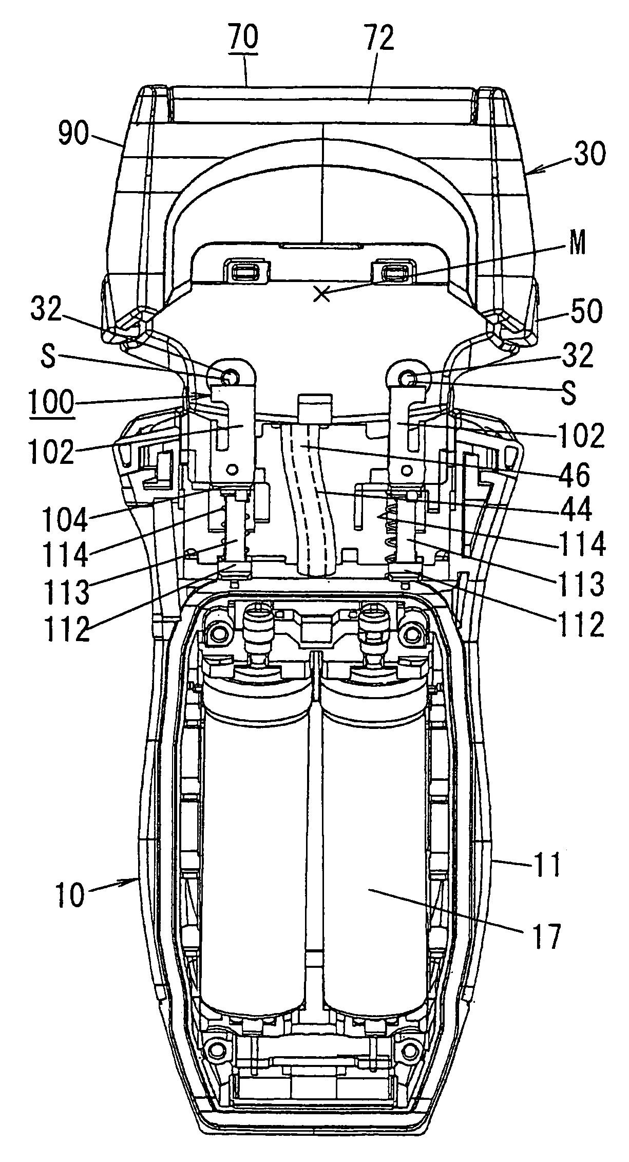
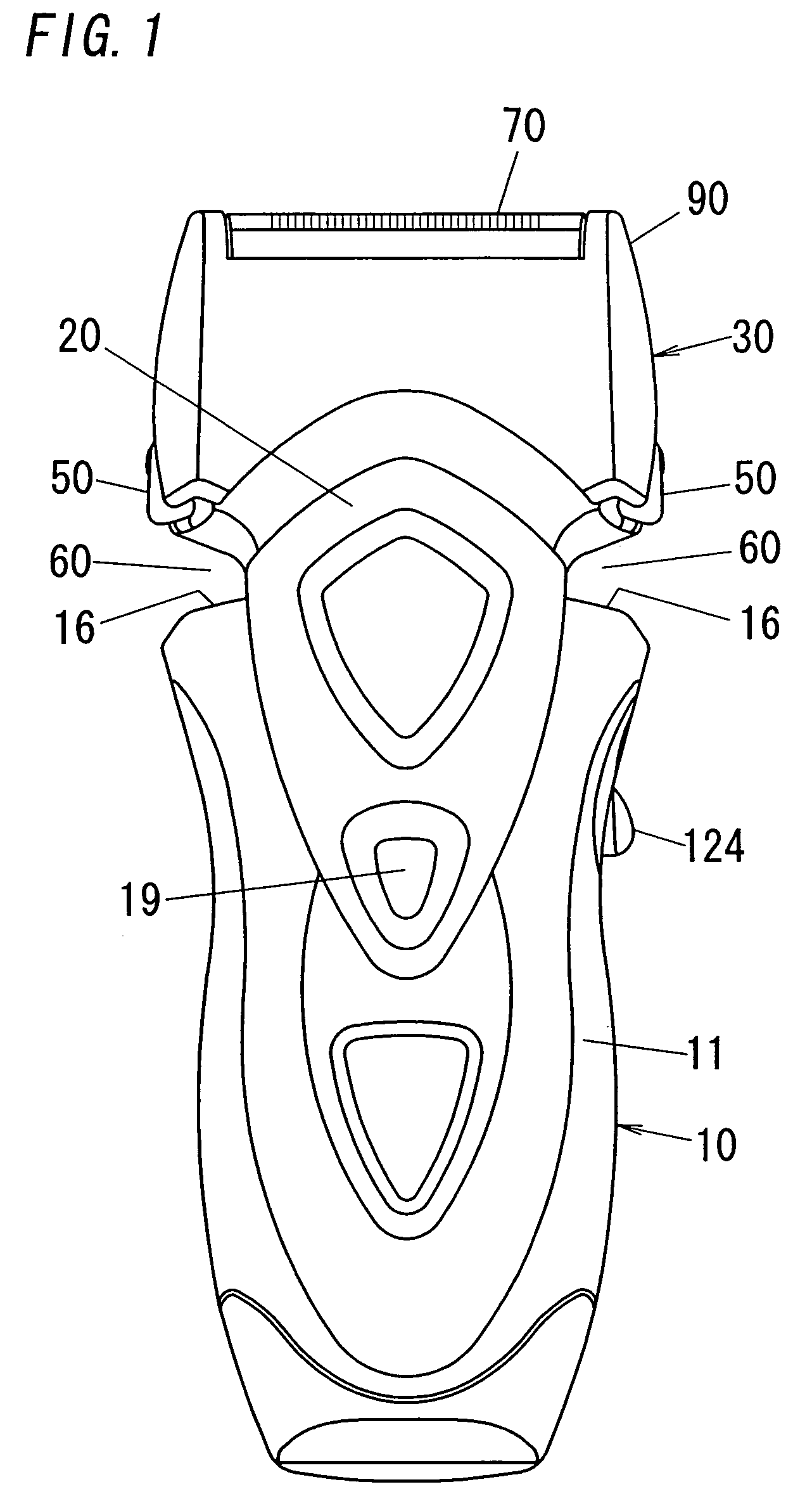
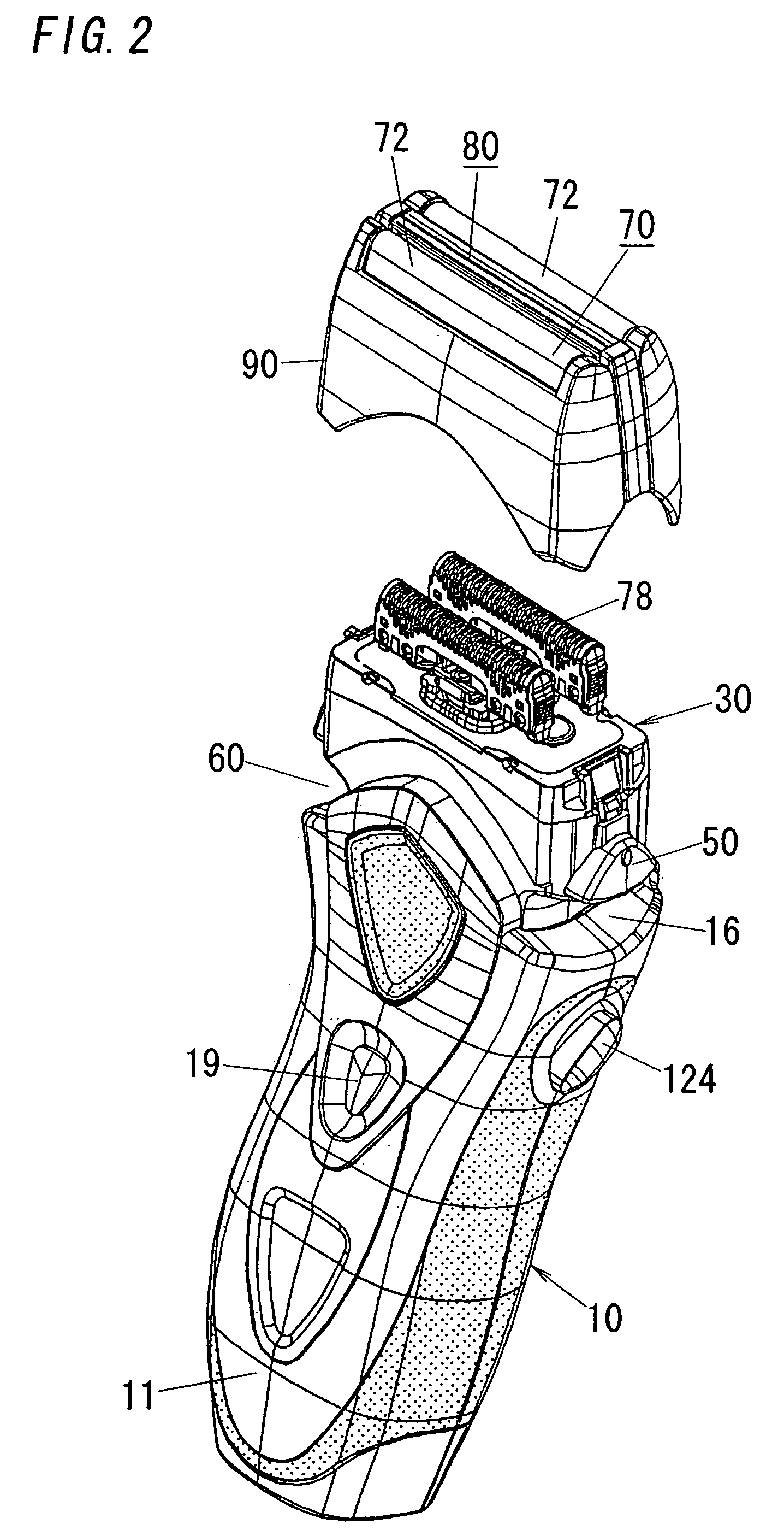
[0046]Referring now to FIGS. 1 to 5, there is shown a dry shaver in accordance with a first embodiment of the present invention. The shaver comprises a hand grip 10 configured to be grasped by a user's hand, and a cradle head 30 carrying three parallel shaving units 70 and 80. Two outer ones of the shaving units 70 are designed for shaving relatively short hairs and each includes an outer cuter 72 in the form of an arcuately curved perforated foil and an inner cutter 78 driven to reciprocate in shearing contact with the outer cutter. The other center shaving unit 80 is designed for shaving relatively long hairs and includes an outer cutter 82 in the form of a slotted piece and an inner cutter 88 driven to reciprocate together with the inner cutters 78 in shearing engagement with the outer cutter 61. The outer cutters 72 of the two outer shaving units 70 and the center shaving unit 80 are integrated into a cutter holder 90 which is detachably coupled to the cradle head 3...

second embodiment

FIGS. 22 and 23

[0059]FIGS. 22 and 23 show a dry shaver in accordance with a second embodiment of the present invention which is identical to the first embodiment except that a cradle head 30A is tilted about a single tilt axis relative to a hand grip 10A. Like parts are designated by like reference numerals with a suffix letter of “A”. In this embodiment, the cradle head 30A is formed at its width center with a pin 34A. The pin 34A is located below an overall mass center M of the cradle head 30A, and is joined to the upper end of the top guard 20A of the hand grip 10A to define the single tilt axis P below the mass center M. In this connection, the support mechanism 100A is configured such that the levers 102 have their upper ends in slidable contact with the corresponding pins 32A at the lower end of the cradle head 30A to allow the pins 32A to move horizontally relative to the corresponding levers 102A while depressing the levers 102A, thereby assuring the tilting movement of the ...

third embodiment

FIGS. 24 to 32

[0060]FIG. 24 shows a dry shaver in accordance with a third embodiment of the present invention which is identical to the first embodiment except that an adjustor dial 120B is provided for variably adjusting a spring bias against which a cradle head 30B is depressed or caused to tilt relative to a hand grip 10B. Like parts are designated by like reference numerals with a suffix letter of “B”. The cradle head 30B, which carries a plurality of the shaving units 70B and 80B and incorporates the motor 40B in much the same manner as in the first embodiment, is movably supported by a like support mechanism 100B to the hand grip 10B incorporating the batteries 17B and a driving circuitry for the motor 40B.

[0061]The support mechanism 100B is provided for allowing the cradle head 30B to tilt and / or be depressed relative to the hand grip 10B, and includes a pair of horizontally spaced levers 102B which are pivotally connected respectively at their upper ends to pins 32B projecti...


PUM


Abstract

A dry shaver has a cradle head carrying shaving units as well as a motor for driving the shaving units. The cradle head is supported to a hand grip such that it is allowed to tilt about at least one tilt axis parallel to a thickness direction of the hand grip. At least one portion of the motor projects upwardly of the tilt axis, whereby the cradle head is given overall mass center which is located upwardly of the tilt axis with respect to the height axis of the hand grip. Accordingly, the motor of heavy nature can be best utilized to locate the overall mass center of the cradle head above the tilt axis for generating a torque acting to tilt the cradle head from a neutral position about the tilt axis when the hand grip is held upright.

Description

TECHNICAL FIELD[0001]The present invention relates to a dry shaver with a cradle shaving head, and more particularly to the shaver having the cradle shaving head tilting about a thickness axis of a shaver for enhanced smooth shaving contact with a user's skin.BACKGROUND ART[0002]A shaver with the cradle shaving head is known in the art, for example, in Japanese Patent Early Publication No. 6-343776 in which the cradle head carrying shaving units is mounted on top of a hand grip and is allowed to tilt about a thickness axis of the hand grip. A motor for driving inner cutters of the shaving units is attached to the lower end of the cradle head, and projects into an upper interior space of the hand grip. Since the motor tilts together with the cradle head, the hand grip is required to give a relatively wide dimension to the upper interior space for accommodating the tilt movement of the motor, thereby necessitating also a wide dimension to the hand grip which is a hindrance to making t...

Claims


Application Information

Patent Timeline
IPC IPC(8): B26B19/04B26B19/10B26B19/38
CPCB26B19/046B26B19/048B26B19/3886B26B19/3826B26B19/3853B26B19/3866B26B19/102B26B19/10B26B19/04
Inventor SHIBA, TAKESHITANIGUCHI, FUMIOMOTOHASHI, RYOYAMASAKI, MASANOBU
Owner MATSUSHITA ELECTRIC WORKS LTD
Why Eureka
Try Eureka