No interrupt service tee and method

a technology of service tee and conduit, which is applied in the direction of branching pipes, manufacturing tools, transportation and packaging, etc., can solve the problems of high undesirable interruption of gas service during main and/or service line replacement operation, corroded elements and need replacement, and large amount of air entering the gas transmission circui

a technology of service tee and conduit, which is applied in the direction of branching pipes, manufacturing tools, transportation and packaging, etc., can solve the problems of high undesirable interruption of gas service during main and/or service line replacement operation, corroded elements and need replacement, and large amount of air entering the gas transmission circui

US7021328B2Inactive Publication Date: 2006-04-04ELSTER PERFECTION CORP

Image

  • No interrupt service tee and method
  • No interrupt service tee and method
  • No interrupt service tee and method

Examples


Embodiment Construction

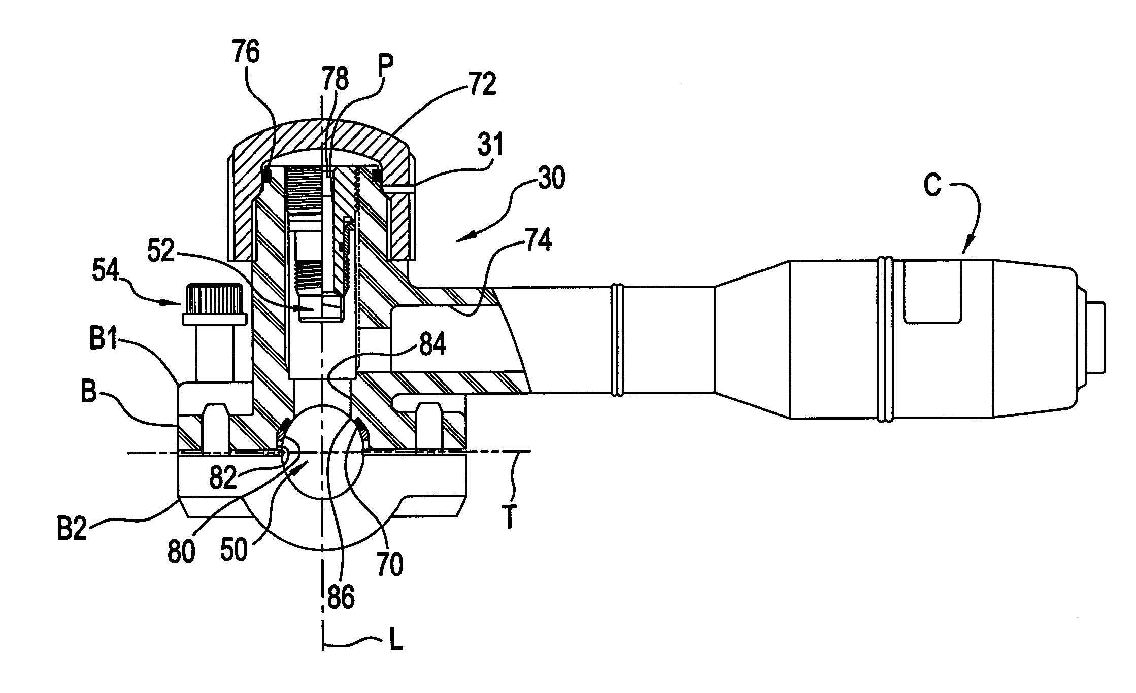
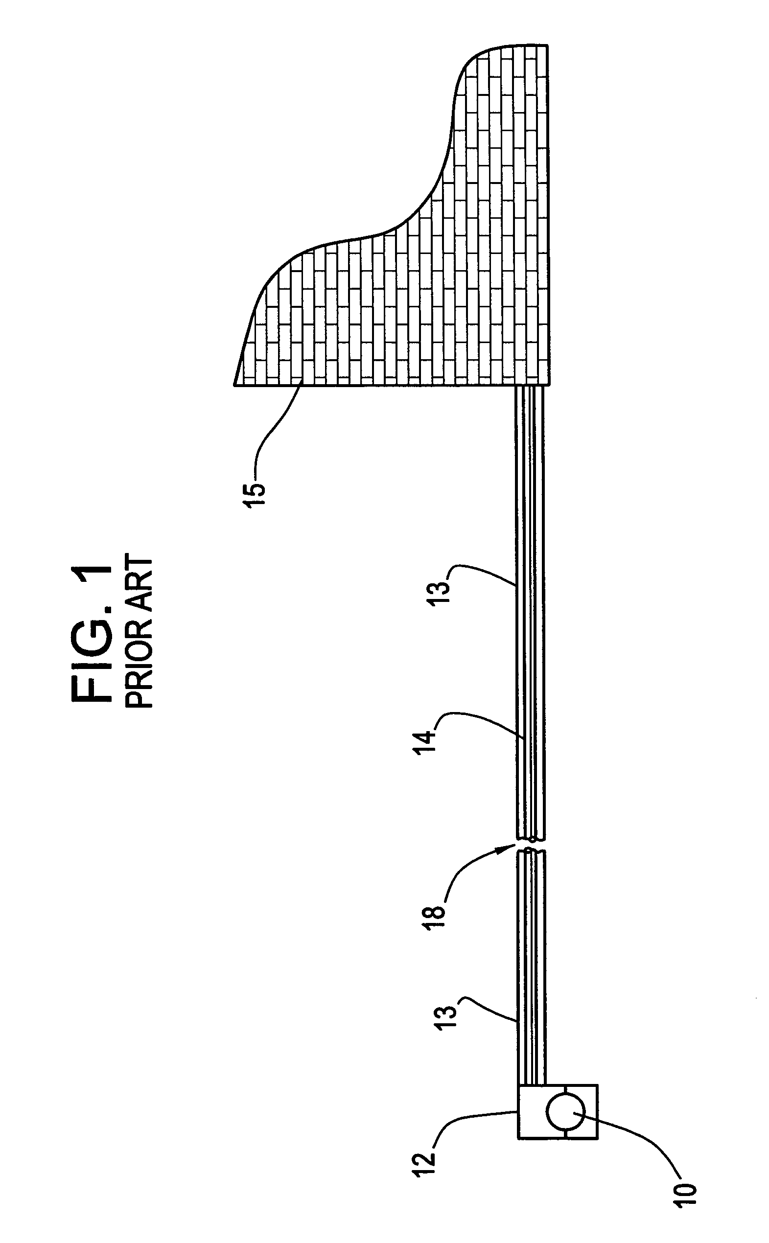
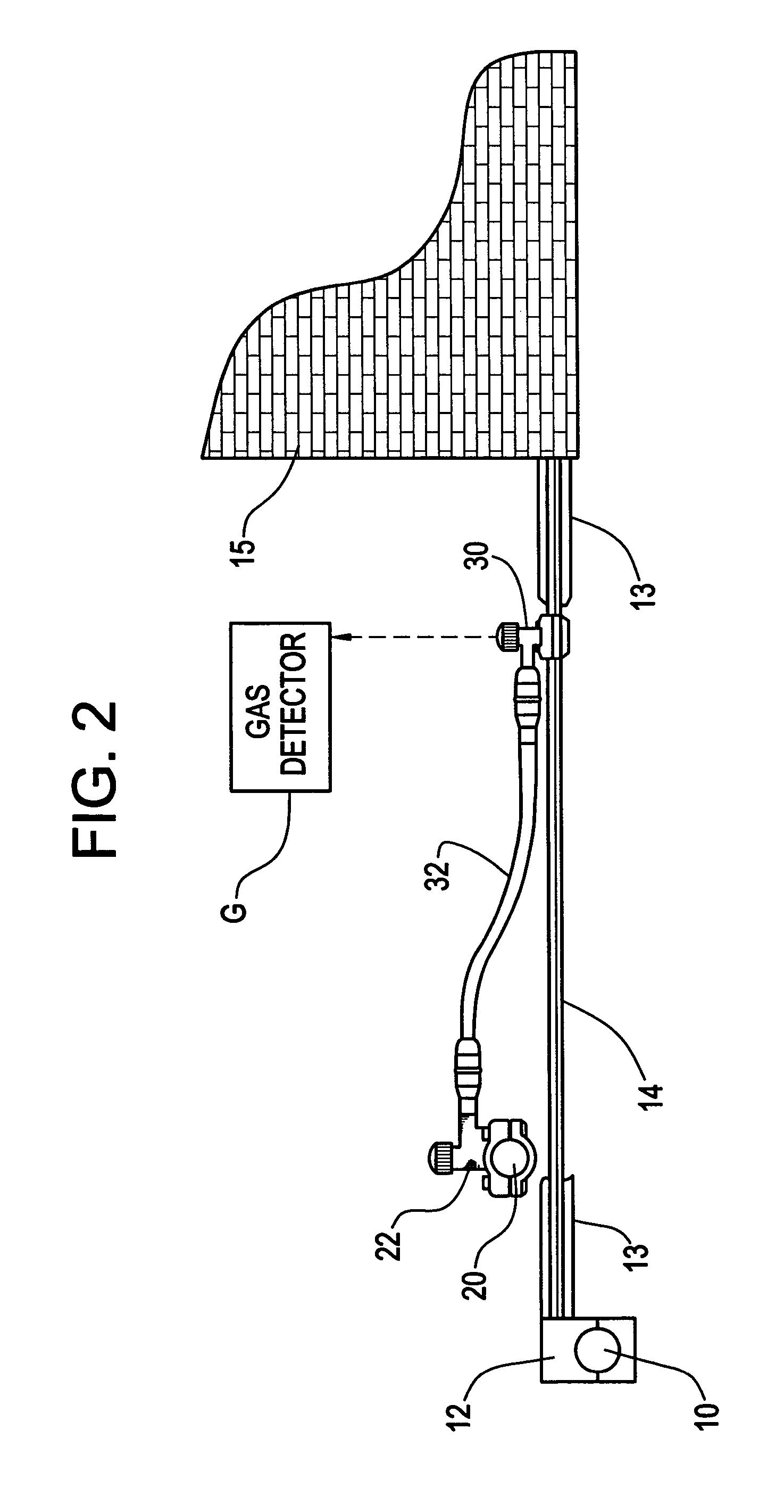
[0028]Referring now to FIGS. 2–8 of the drawings, wherein the showing are for purposes of disclosing preferred embodiments only and not for purposes of limiting same, FIG. 2 illustrates the previously described conventional gas installation, along with a replacement main conduit 20 and interconnecting service line conduit 32 that are intended to replace the existing main 10 and part of the existing service line 14, respectively. With reference also to the flow-chart of FIG. 8, the method comprises a step S1 of installing a tapping tee 22 on the new main 20, without tapping the new main. The method further comprises a step S2 of installing a second, specially configured “No Interrupt Service Tee” (NIST) 30 (described below) on the existing service line 14, preferably at a location adjacent the recipient 15 (the outer, metallic conduit 13, if any, is removed from the existing plastic service line conduit 14 as needed for access to the plastic service line conduit 14). Here, again, the...


PUM

PropertyMeasurementUnit
outer diameteraaaaaaaaaa
flexibleaaaaaaaaaa

Abstract

A method of replacing a gas main that supplies gas to a recipient through an existing service line includes connecting a first tapping tee to the new gas main and connecting a second tapping tee to the existing service line that communicates with a downstream recipient. Branch passages of the first and second tapping tees are fluidically connected together by a connecting conduit. The new gas main is then tapped with the first tee so that gas flows from the new gas main into the connecting conduit up to the second tee. All air is bled from the connecting conduit between the first and second tees, and the existing service line is then tapped with the second tee so that gas is supplied to the recipient through both the existing service line and the connecting conduit. Gas flow to the recipient from the old main is then terminated. The second tee is a specially configured tapping tee specifically adapted for bleeding air from the connecting conduit that interconnects the first and second tees. This tee also utilizes a non-cylindrical bore for holding the conduit to be tapped to inhibit collapsing of the conduit during tapping operations.

Description

CROSS-REFERENCE TO RELATED APPLICATION[0001]This application is a continuation of application Ser. No. 09 / 611,142 filed Jul. 6, 2000, now U.S. Pat. No. 6,612,330.BACKGROUND OF THE INVENTION[0002]The present invention relates generally to the art of tapping conduits and, more particularly, to the art of tapping mains and service lines for purposes of replacing same without interrupting service. The invention will be described in connection with gas mains and service lines, but those of ordinary skill in the art will quickly recognize that the invention has broader application to other mains and service lines, especially those designed to supply a fluid to a recipient in a non-interruptible fashion.[0003]In the installation of new natural gas mains, it is typical to bury the new main in the desired location (usually in parallel with an existing main) and thereafter connect the existing or new service lines thereto for purposes of supplying gas to recipients by way of respective servic...

Claims


Application Information

Patent Timeline
04 Apr 2006
Publication
US7021328B2
IPC
F16K43/00; F16L41/06; F16L55/16
CPC
F16L41/06; F16L55/1604; Y10T408/6793; Y10T137/0469; Y10T137/6123
Inventors
ROBISON, DAVID L.; BRZOZOWSKI, GREGORY ALAN